
Membrane humidifier for fuel cell

a fuel cell and humidifier technology, applied in membrane technology, membranes, electrochemical generators, etc., can solve the problems of deteriorating humidification efficiency for dry air, difficult for wet air to penetrate the interiors of hollow fiber membranes, slow rate of wet air through hollow fiber membranes, etc., to improve vehicle humidification performance and improve the distribution of wet air

Active Publication Date: 2013-03-14
HYUNDAI MOTOR CO LTD +1
View PDF5 Cites 16 Cited by
  • Summary
  • Abstract
  • Description
  • Claims
  • Application Information

AI Technical Summary

Benefits of technology

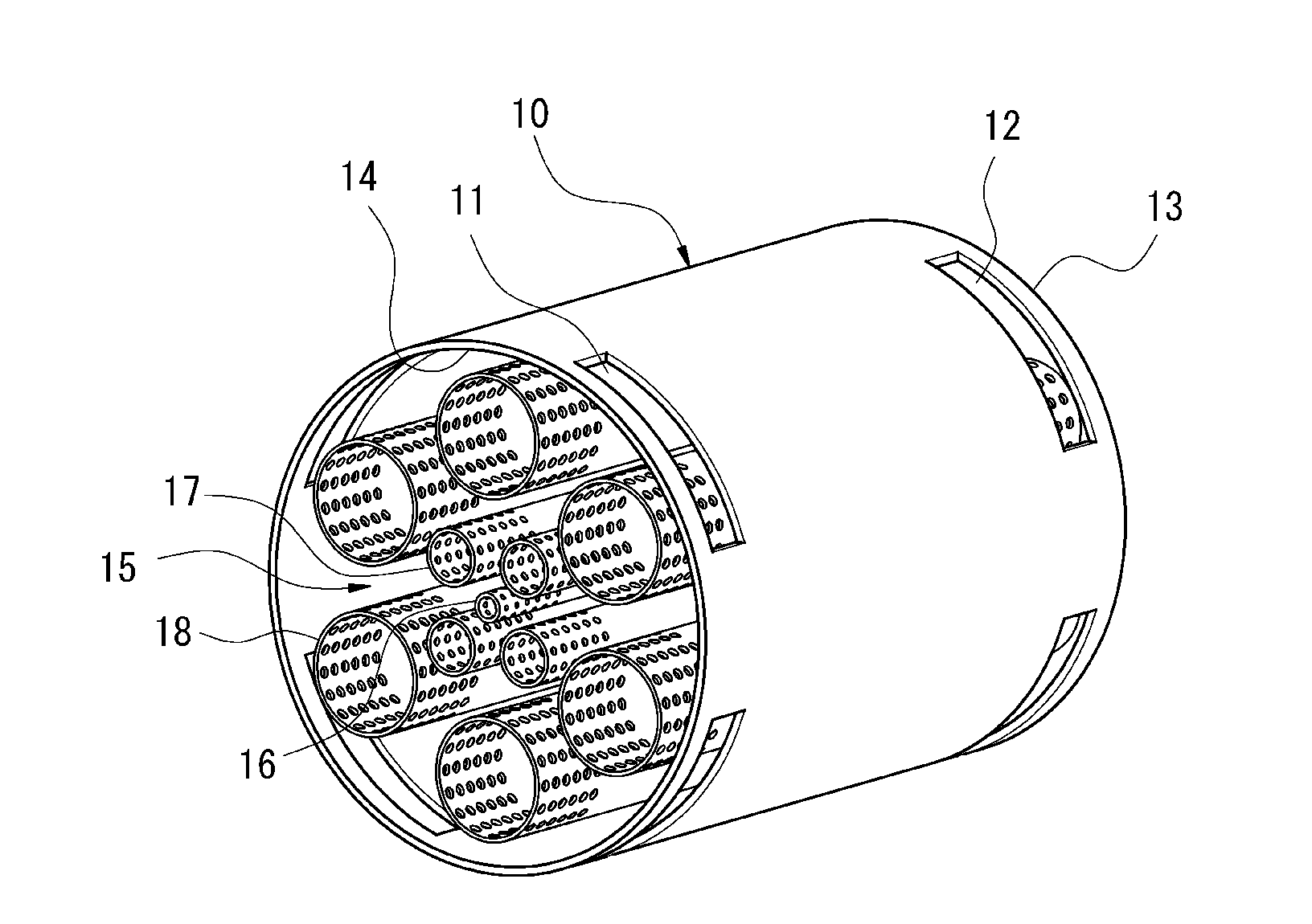
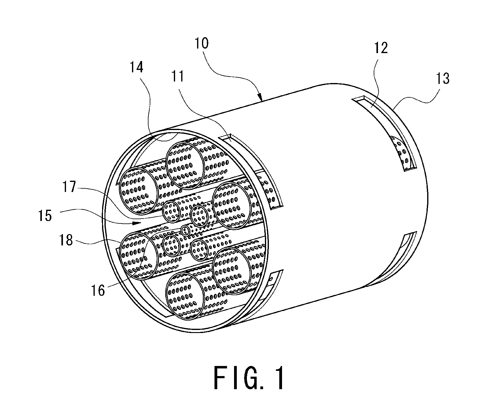
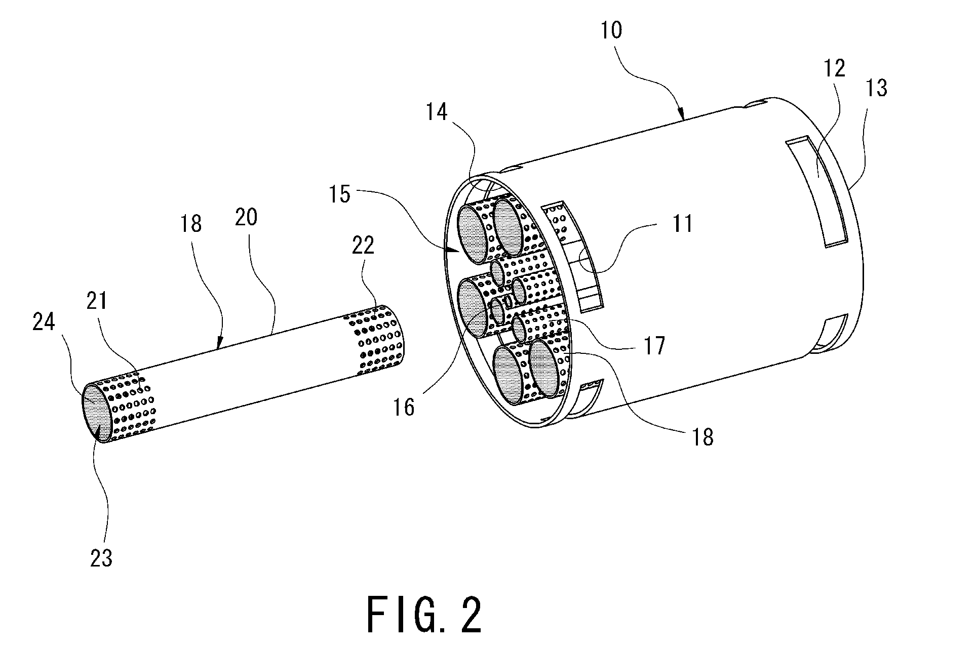
The present invention is a membrane humidifier for a fuel cell that uses cartridge-shaped unit membrane modules of different diameters to improve the distribution of wet and dry air. This results in the entire dry air from the outer edge to the center of the module being uniformly humidified, which enhances the humidification performance of the fuel cell. In summary, this invention improves the air humidification performance of a fuel cell by using membrane modules of various diameters to achieve better distribution of wet and dry air.

Problems solved by technology

However, since there is only a limited space on the package surface of a fuel cell vehicle, a small-sized membrane humidifier requiring no special power is used in the fuel cell.
Further, the diffusion rate of the wet air through the hollow fiber membranes is very slow, and thus it is very difficult for the wet air to permeate into the interiors of the hollow fiber membranes.
Thus, the diffusion rate of the wet air to the central portion of the hollow fiber membrane bundle 107 is very slow, thereby causing deterioration of humidification efficiency for dry air.
Thus, due to the above problems, the hollow fiber membranes 106 located at the central portion of the hollow fiber membrane bundle 107 fail to receive a sufficient amount of moisture, thus deteriorating general efficiency of the humidifier.
Accordingly, the humidification efficiency of the membrane humidifier is deteriorated, which further affects when the flow of the dry air is increased, i.e., a high power is output from the fuel cell stack.
Therefore, in cold weather, water introduced into the membrane humidifier freezes and prevents the hollow fiber membranes from suitably performing its humidification activity.
Further, since surfaces of the hollow fiber membranes of the conventional membrane humidifier are repeatedly frozen and melted, the hollow fiber membranes on the outer sides, i.e., the edge portions, of the hollow fiber membrane bundle 107 through which the wet air mainly flows are damaged or become disconnected (see FIG. 9).
Even further, if the surfaces of the hollow fiber membranes are repeatedly frozen and melted to the extent that they become damaged, the damaged hollow fiber membranes eventually have a drastic effect on a performance of the fuel cell stack, and thus it is necessary to change the entire membrane humidifier.
Additionally, in manufacturing of the membrane humidifier, a large portion of the membrane humidifier is made of expensive hollow fiber membranes formed of a polymer material.
In order to improve the humidification performance, more hollow fiber membrane bundles are used than necessary, thus increasing the manufacturing cost.
In addition, due to the use of many hollow fiber membrane bundles, the size of the membrane humidifier is disproportionate compared to the performance of the membrane humidifier.
Furthermore, since the conventional membrane humidifier includes a single hollow fiber membrane module within which a plurality of hollow fiber membranes is received in the form of a bundle, the hollow fiber membranes are not uniformly distributed within the housing and are weighted to one side of the housing during manufacturing the membrane humidifier (see FIG. 10).

Method used


Image

  • Membrane humidifier for fuel cell
  • Membrane humidifier for fuel cell
  • Membrane humidifier for fuel cell

Examples


Embodiment Construction

[0035]Hereinafter reference will now be made in detail to an embodiment of the present invention, examples of which are illustrated in the accompanying drawings and described below.

[0036]It is understood that the term fuel cell “vehicle” or “vehicular” or other similar term as used herein is inclusive of all types of fuel cell motor vehicles in general such as passenger automobiles including sports utility vehicles (SUV), buses, trucks, various commercial vehicles, watercraft including a variety of boats and ships, aircraft, and the like, and includes hybrid fuel cell vehicles, electric motor powered fuel cell vehicles, auxiliary plug-in fuel cell hybrid electric vehicles, hydrogen-powered fuel cell vehicles and other alternative fuel cell vehicles (e.g., fuels derived from resources other than petroleum).

[0037]As already described with reference to FIG. 6, the conventional membrane humidifier for the fuel cell humidifies dry air through moisture exchange using the hollow fiber memb...


PUM

PropertyMeasurementUnit
diametersaaaaaaaaaa
diameteraaaaaaaaaa
timeaaaaaaaaaa

Abstract

Disclosed is a membrane humidifier for a fuel cell, which uniformly humidifies entire hollow fiber membranes from an outer side to a central portion of an interior of the membrane humidifier to improve the distribution of wet air and dry air, thereby improving a humidification performance. The membrane humidifier for the fuel cell includes a hollow upper case including first wet air inlet apertures and first wet air outlet apertures and a membrane module assembly including a plurality of unit membrane modules received lengthwise within the upper case along the flow direction of dry air.

Description

CROSS-REFERENCE TO RELATED APPLICATION[0001]This application claims under 35 U.S.C. §119(a) the benefit of Korean Patent Application No. 10-2011-0092686 filed Sep. 14, 2011, the entire contents of which are incorporated herein by reference.BACKGROUND[0002](a) Technical Field[0003]The present invention relates to a membrane humidifier for a fuel cell. More particularly, it relates to a membrane humidifier for a fuel cell, which uniformly humidifies entire hollow fiber membranes from outer sides of the membrane to a central portion of the interior of the membrane humidifier to improve the distribution of wet air and dry air, thereby improving the humidification performance.[0004](b) Background Art[0005]Fuel cell stack operation requires humidifying a polymer electrolyte membrane within the fuel cell stack. Accordingly, the fuel cell employs a membrane humidifier operated by moisture exchange between moisture from exhaust gas, which is a wet air discharged from the fuel cell stack, and...

Claims


Application Information

Patent Timeline
Patent Type & Authority Applications(United States)
IPC IPC(8): H01M8/06
CPCB01D63/04B01D2319/04H01M8/04149H01M8/04141Y02E60/50B01D65/00B01D69/08H01M8/04
Inventor KIM, HYUN YOOKWON, HYUCK ROUL
Owner HYUNDAI MOTOR CO LTD
Learn More