
Pump Assembly, System and Method for Controlled Delivery of Molten Metal to Molds

a pump and molten metal technology, applied in the direction of machines/engines, packaging, liquid transferring devices, etc., can solve the problems of insufficient filling of molds to required fill metrics, inherently difficult to control the head pressure of molten metal, and insufficient use of centrifugal pumps

Active Publication Date: 2013-03-21
PYROTECK INC
View PDF10 Cites 24 Cited by
  • Summary
  • Abstract
  • Description
  • Claims
  • Application Information

AI Technical Summary

Benefits of technology

The patent describes a pump assembly that can control the speed of an impeller to precisely control the flow of molten metal. This allows for precise fill profiles in scenarios such as casting applications. The pump assembly also facilitates a continuous supply of molten metal to holding furnaces without the need to interrupt operations. The invention is a revolutionary technique for controlled delivery of molten metal to molds and improves the process of filling complex molds without casting defects.

Problems solved by technology

However, when it comes to applications such as casting (i.e., filling molds with molten metal) or molten metal dosing, centrifugal pumps have not been used as a means for filling molds.
However, these solutions suffer from drawbacks which make them insufficient for filling molds to required fill metrics.
However, due to the fact that air is a highly compressible medium, it is inherently difficult to control the head pressure of the molten metal 104 with a pressurized furnace.
This is impractical and inefficient for mass production applications in casting.
However, EMPs are expensive relative to centrifugal pumps or similar equipment capable of accomplishing the same task.
Additionally, EMPs, like pressurized furnaces, are also difficult to control with respect to accurate delivery of the molten metal.

Method used


Image

  • Pump Assembly, System and Method for Controlled Delivery of Molten Metal to Molds
  • Pump Assembly, System and Method for Controlled Delivery of Molten Metal to Molds
  • Pump Assembly, System and Method for Controlled Delivery of Molten Metal to Molds

Examples


Embodiment Construction

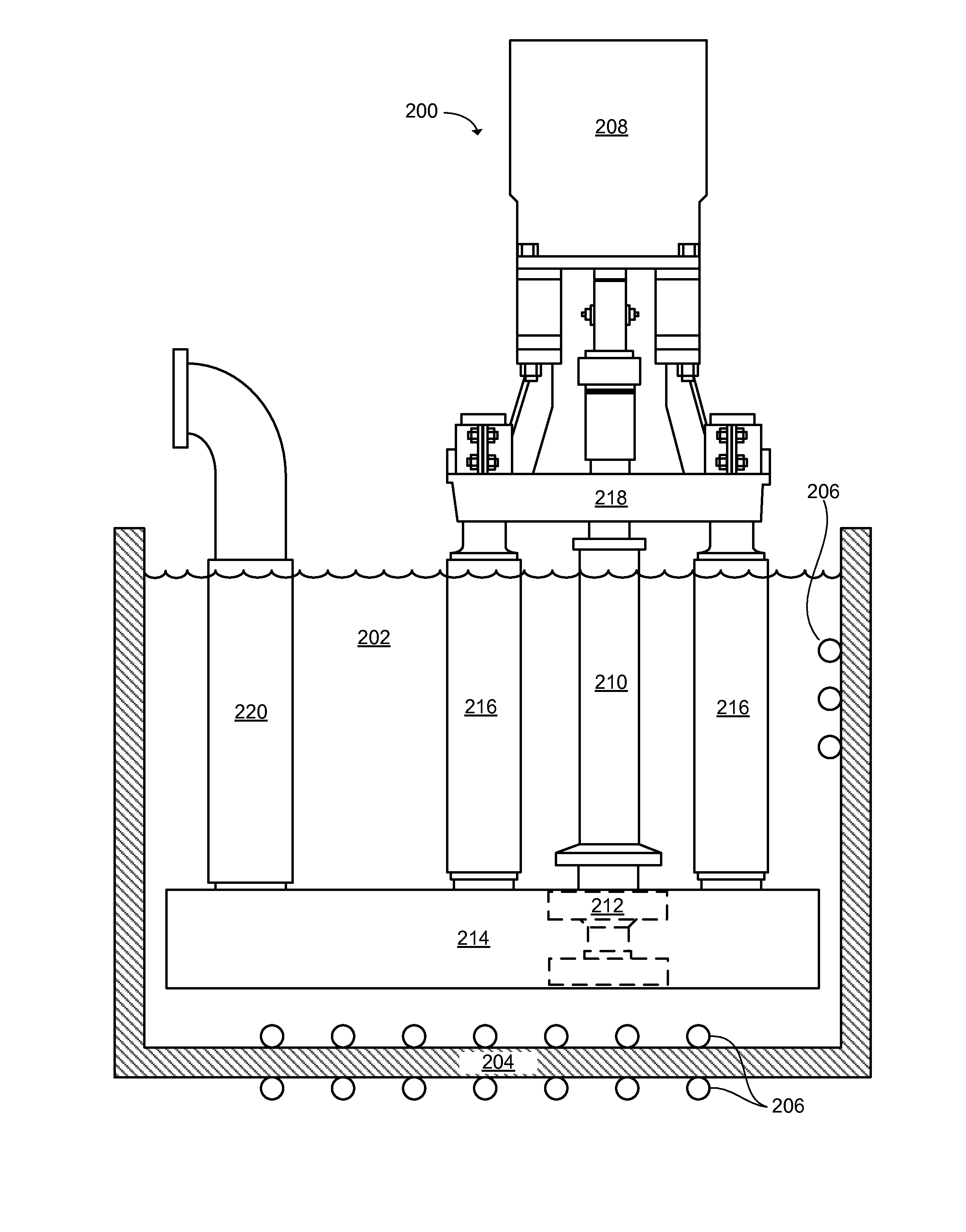
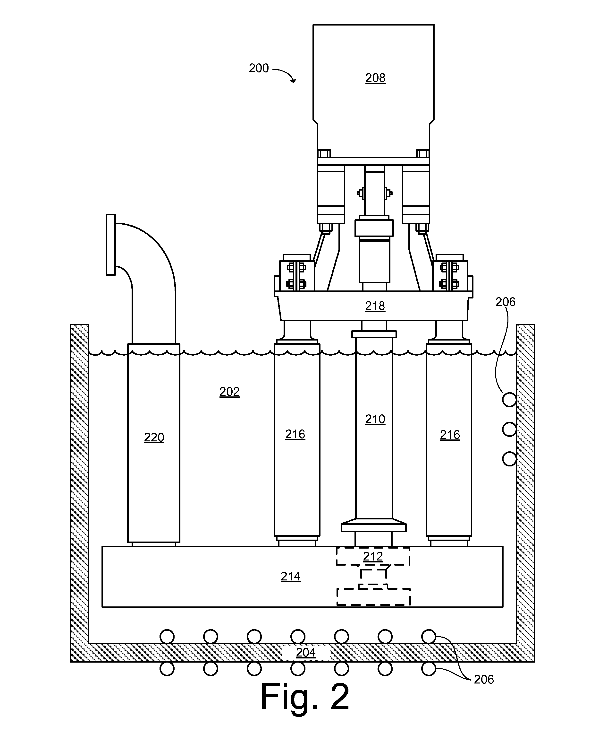
[0024]Referring to FIG. 2, there is illustrated a centrifugal molten metal pump assembly 200 (hereinafter “pump assembly”200) according to an example embodiment. As used herein, the terms “centrifugal pump” and “circulation pump” may be used interchangeably to describe the molten metal pump utilized in the pump assembly 200 and described in the embodiments disclosed herein. “Centrifugal pumps” are meant to include any type of variable pressure pump comprising a shaft and impeller assembly.

[0025]The pump assembly 200 is shown from a side view submerged in a bath of molten metal 202 which is contained in an open holding furnace 204, or tank (shown from a cross sectional view). As used herein, the term “molten metal” will be understood to mean any metal, such as aluminum, copper, iron, and alloys thereof, which are amendable for casting, dosing or similar applications. The molten metal 202 may be maintained in its molten or liquid state by heating elements 206 disposed in any suitable ...


PUM

PropertyMeasurementUnit
Temperatureaaaaaaaaaa
Pressureaaaaaaaaaa
Flow rateaaaaaaaaaa

Abstract

Disclosed is a centrifugal molten metal pump assembly and associated system for controlled delivery of molten metal to molds. The pump assembly comprises a shaft, an impeller coupled to the shaft, a controller to control a rotational speed of the impeller according to a programmable fill profile while delivering the molten metal to the mold. In some embodiments, the pump assembly further comprises a throttle to manipulate a flow rate or pressure of the molten metal relative to a rotational speed of the impeller. The associated system comprises a melting furnace and one or more holding furnaces, each holding furnace including at least one pump assembly therein. Each holding furnace may be of an open configuration to allow for uninterrupted flow of the molten metal from the melting furnace. The system may provide controlled delivery of the molten metal to the mold at a desired flow rate or pressure.

Description

RELATED APPLICATIONS[0001]This application is a continuation-in-part of, and claims priority to, PCT Application No. PCT / US2012 / 034048, filed on Apr. 18, 2012, entitled, “MOLD PUMP ASSEMBLY,” which is based on and claims priority to U.S. Provisional Application No. 61 / 476,433, filed on Apr. 18, 2011, entitled, “MOLD PUMP ASSEMBLY,” the contents of which are herein incorporated by reference.BACKGROUND[0002]1. Field of the Invention[0003]The present invention relates generally to molten metal pump systems, and in particular, to a molten metal pump assembly and associated system for controlled delivery of molten metal to molds.[0004]2. Description of Related Art[0005]Various applications exist where liquid or molten metal needs to be moved. Molten metal pumps are an effective way of accomplishing this task. For instance, centrifugal pumps (sometimes referred to as circulation pumps) have been used to circulate molten metal within a container, and to transfer molten metal from one locat...

Claims


Application Information

Patent Timeline
IPC IPC(8): B22D39/02F04D3/00B22D23/00
CPCB22D17/02F04D7/065F04D29/0473F04D7/00B22D39/02F04D3/005B22D23/00F04D7/04F04D7/06F04D29/047
Inventor TIPTON, JONHENDERSON, RICHARD S.
Owner PYROTECK INC
Features
  • Generate Ideas
  • Intellectual Property
  • Life Sciences
  • Materials
  • Tech Scout
  • Unparalleled Data Quality
  • Higher Quality Content
  • 60% Fewer Hallucinations
Learn More