Eureka AIR delivers breakthrough ideas for toughest innovation challenges, trusted by R&D personnel around the world.

Capacitor element and capacitor device having the same

Active Publication Date: 2013-03-21
TAIYO YUDEN KK
View PDF7 Cites 1 Cited by
  • Summary
  • Abstract
  • Description
  • Claims
  • Application Information

AI Technical Summary

Benefits of technology

The present invention provides a stacked capacitor with a high withstand voltage and large capacitance, and a capacitor forming unit for forming the capacitor. The capacitor forming unit includes a dielectric plate with multiple through holes, two layers of conductor film, two layers of insulator film, and one or more electrode rods. The electrodes are connected to the corresponding conductor film and insulated from each other. The capacitor is designed to have equal size to conventional capacitors but with higher performance. In addition, an insulating cover film is provided to protect the capacitor from external environmental factors. The invention allows for the formation of a stacked capacitor with high withstand voltage and high capacitance, providing a solution for high-performance electronic devices.

Problems solved by technology

However, a problem is that the external size increases with changes of the materials and thickness of the internal electrode layers and the dielectric layers.

Method used


Image

  • Capacitor element and capacitor device having the same
  • Capacitor element and capacitor device having the same
  • Capacitor element and capacitor device having the same

Examples


Embodiment Construction

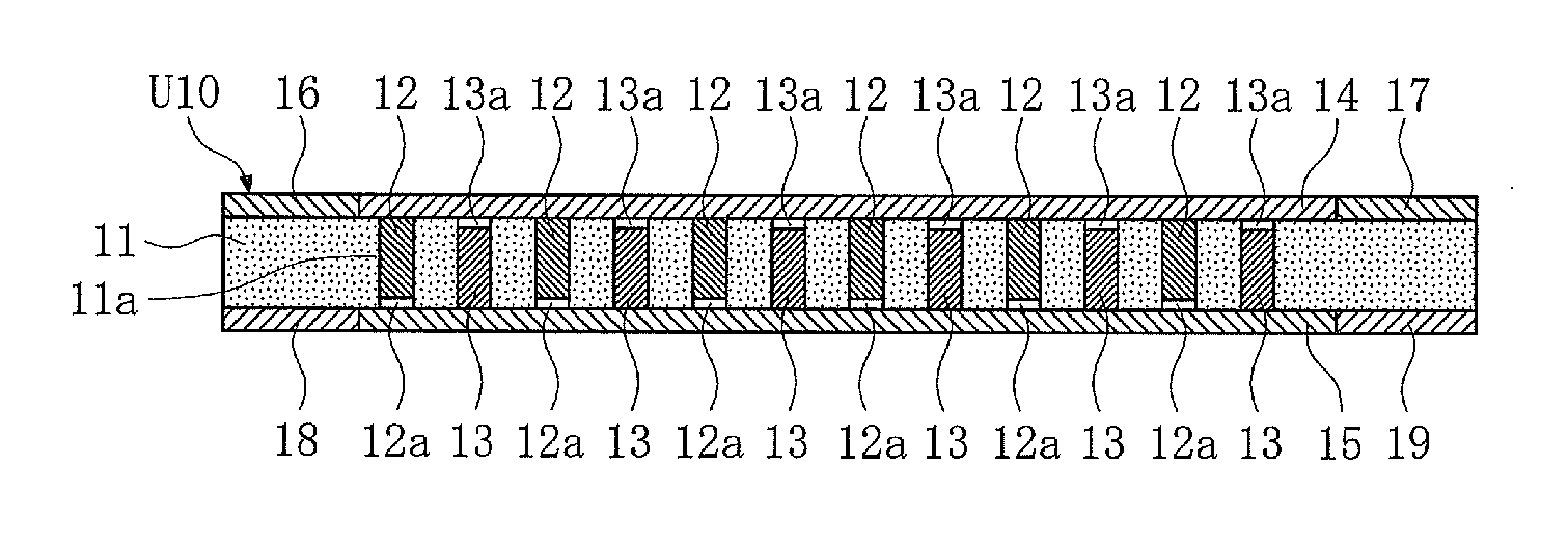
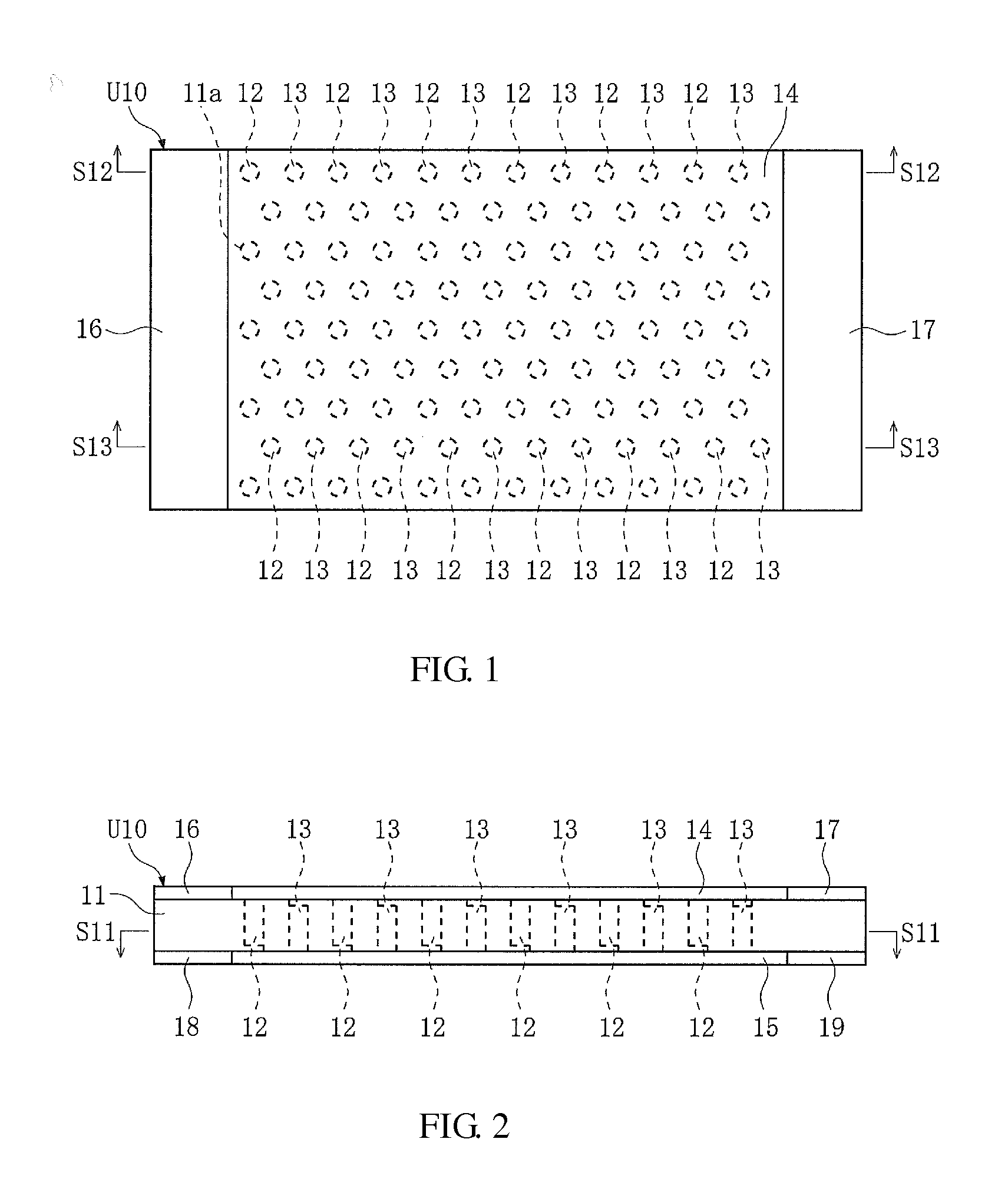
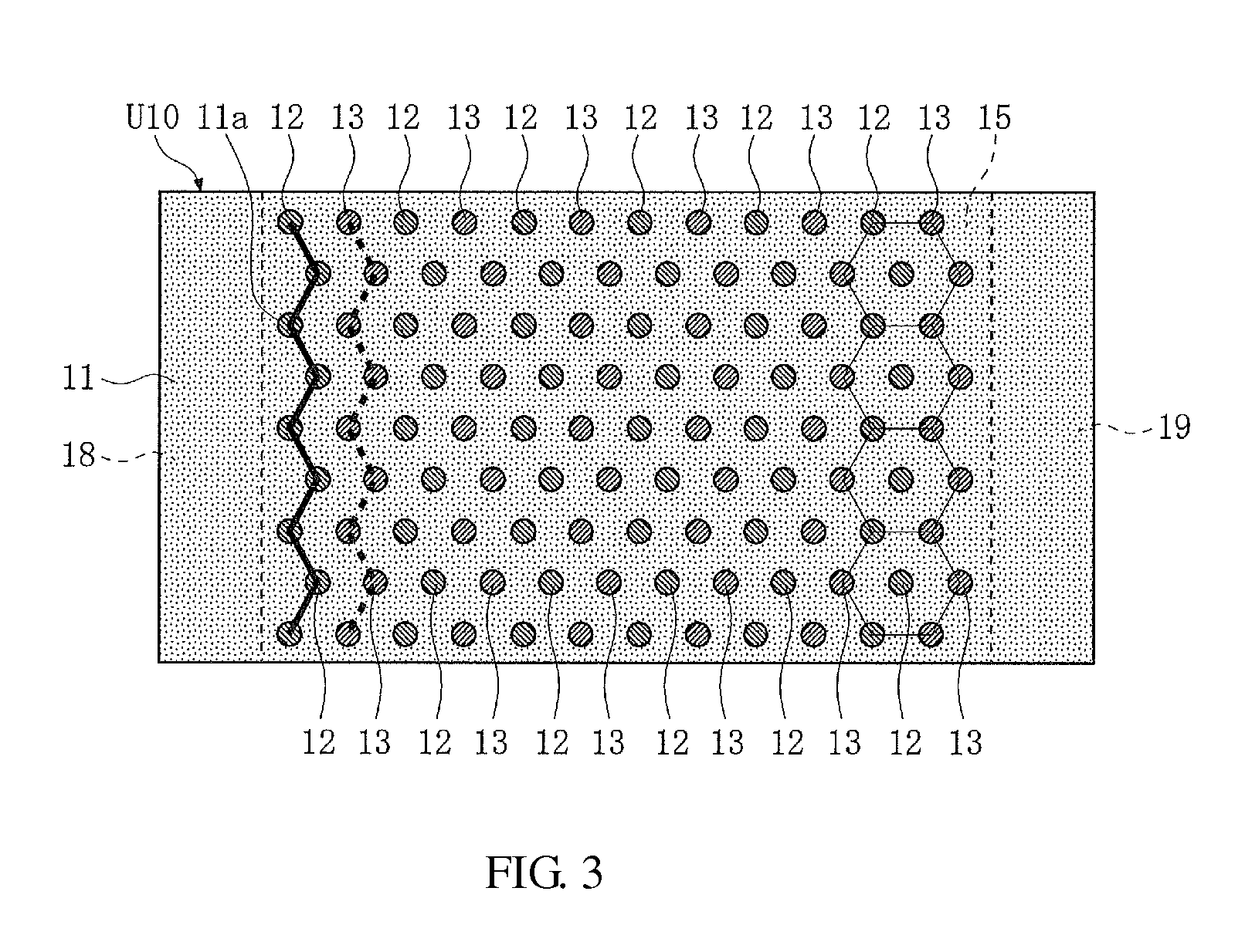
[0034]A capacitor forming unit U10 according to an embodiment of the present invention will be described with reference to FIGS. 1 to 9. In this specification, the left, right, bottom, top, front and rear sides as viewed in FIG. 1 will be referred to as the front, rear, left, right, top and bottom, respectively, for ease of description. The sides shown in FIGS. 2 to 9 are also designated in accordance with this orientation.

[0035]The unit U10 according to an embodiment of the present invention shown in FIGS. 1 to 5 has a dielectric plate 11, first electrode rods 12, second electrode rods 13, a first conductor film 14, a second conductor film 15, a first insulator film 16, a second insulator film 17, a third insulator film 18 and a fourth insulator film 19. By using this unit U10, a capacitor of the 0603 size for example can be made. The capacitor size is not limited to the 0603 size. For example, a capacitor of a size such as the 0402 size smaller than the 0603 size can be made by re...


PUM


Abstract

A capacitor forming unit includes a dielectric plate, a first conductor film formed on a plate upper surface region other than front and rear end portions, a first insulator film formed on the upper surface front end portion, a second insulator film formed on the upper surface rear end portion, a second conductor film formed on a plate lower surface region other than front and rear end portion, a third insulator film formed on the front end portion lower surface, and a fourth insulator film formed on the lower surface rear end portion. One or more first electrode rods are disposed in through holes, and electrically connected to the first conductor film and electrically insulated from the second conductor film. One or more second electrode rods are disposed in other through holes, and electrically connected to the second conductor film and electrically insulated from the first conductor film.

Description

BACKGROUND OF THE INVENTION[0001]1. Field of the Invention[0002]The present invention relates to a capacitor forming unit used to form a capacitor and to a capacitor having the capacitor forming unit.[0003]2. Description of the Related Art[0004]Several hundreds of stacked capacitors are used in one electronic device such as a portable telephone, a notebook computer, a video camera or a digital camera. Stacked capacitors have improved mountability onto circuit boards, and have a large capacity although they are small in size. For example, a stacked capacitor of the 0603 size having a capacitance of 0.47 μF (having a rated voltage of 4.0 V) is available in the market. Japanese Patent No. 4493686 discloses a stacked capacitor of a small size and a large capacitance.[0005]In recent years, with the improvement in performance of various electronic devices, there has been a demand for a stacked capacitor of a high withstand voltage (which means an increased rated voltage). In a stacked cap...

Claims


Application Information

Patent Timeline
IPC IPC(8): H01G4/06
CPCH01G4/06H01G4/30H01G4/232H01G4/008H01G4/10H01G4/302
Inventor TAKE, YOSHINARIMASUDA, HIDETOSHIOTA, KENICHI
Owner TAIYO YUDEN KK
Why Eureka
Eureka Blog
Learn More