Converting device of electrical energy

a technology of electrical energy and conversion device, which is applied in the direction of power conversion system, reactive power compensation, circuit arrangement, etc., can solve the problems of increasing the whole manufacturing cost, low power factor, and low cost, and achieves the reduction of harmonic wave, power factor and waveform coefficient of current of the power generation device.

Inactive Publication Date: 2013-03-21
NEW ENERGY POWER
View PDF8 Cites 11 Cited by
  • Summary
  • Abstract
  • Description
  • Claims
  • Application Information

AI Technical Summary

Benefits of technology

[0015]Through the technical solution of the disclosure, by processing the output of each phase of the three-phase AC generated by a power generation device, the waveform coefficient of the current of the power generation device is improved, the harmonic wave is reduced, and the power factor and the utilization rate of the device are improved; by taking a tryristor as a main switch element of a power conversion unit, the electric energy conversion device has a low cost and a high reliability; connected with tryristor three-phase fully-controlled bridge circuits of different grades in serial, the electric energy conversion device can be adapted to power generation devices

Problems solved by technology

Such new energy power generation systems are characterized by decentralized power generation device, small capacity per unit, wide distribution area, and unstable output voltage and current, so how to effectively and reliably feed the electric energy generated by these renewable energy power generation devices back to the power grid at low cost and convert the electric energy generated by these renewable energy power generation devices into three-phase power for direct industrial and civil use is the problem to be

Method used


Image

  • Converting device of electrical energy
  • Converting device of electrical energy
  • Converting device of electrical energy

Examples


Embodiment Construction

[0030]It should be noted that, in the case of no conflict, the embodiments of the disclosure and features therein can be combined with each other. The disclosure will be described below in detail with reference to the drawings and in conjunction with the embodiments.

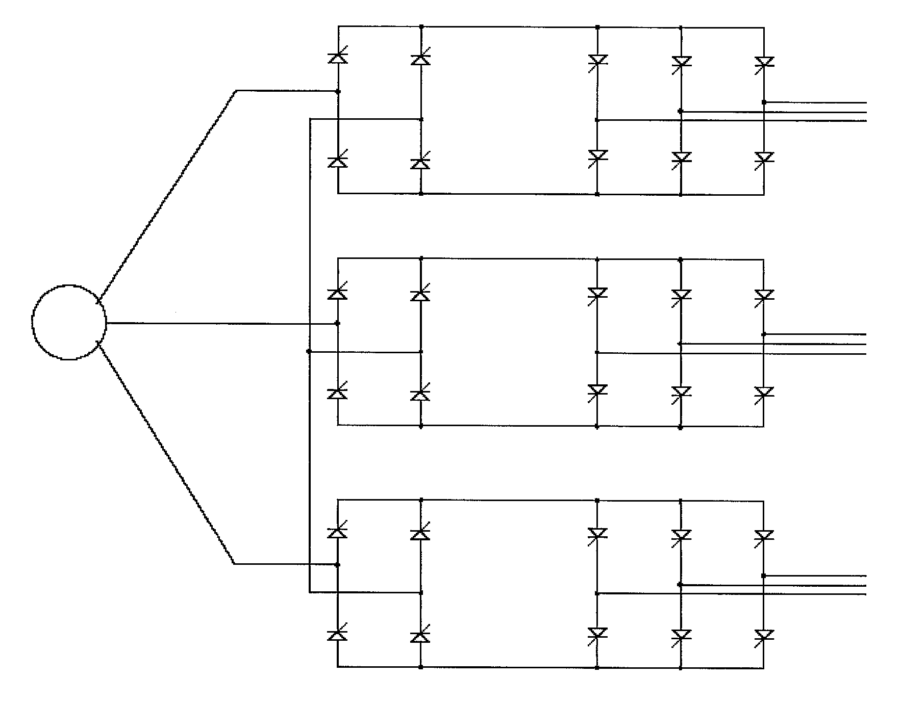
[0031]FIG. 5 is a schematic circuit diagram of a single-phase rectifier bridge circuit in an electric energy conversion device according to the first embodiment of the disclosure.

[0032]As shown in FIG. 5, the electric energy conversion device in the first embodiment of the disclosure is the part in the dashed box 50 in FIG. 5. And this kind of electric energy conversion device includes three rectifier bridge circuits, each of the rectifier bridge circuit includes a first input end and a second input end, for example, in the rectifier bridge circuit in the dashed box 51, the first input end and the second input end are points A and B respectively. In the electric energy conversion device shown in FIG. 5, the second input ...


PUM


Abstract

The disclosure discloses an electric energy conversion device and system, to solve the problems of severe harmonic pollution, low power factor during the electric energy feedback from a power generation device to a power grid in the conventional art. The electric energy conversion device comprises: a plurality of single-phase rectifier bridge circuits, a first input ends of the a plurality of single-phase rectifier bridge circuits, and a second input ends of the a plurality of single-phase rectifier bridge circuits, wherein two input ends of each three-phase fully-controlled bridge circuit are connected with two output ends of each the rectifier bridge circuit respectively. Through the technical solution of the disclosure, the waveform coefficient of the current of the power generation device is improved, the harmonic wave is reduced, and the power factor is improved.

Description

FIELD OF THE INVENTION[0001]The disclosure relates to the technical field of power electronics, in particular, to an electric energy conversion device.BACKGROUND OF THE INVENTION[0002]People pay more attention to the power generation by renewable energy, such as wind power generation, solar power generation and tidal power generation. Such new energy power generation systems are characterized by decentralized power generation device, small capacity per unit, wide distribution area, and unstable output voltage and current, so how to effectively and reliably feed the electric energy generated by these renewable energy power generation devices back to the power grid at low cost and convert the electric energy generated by these renewable energy power generation devices into three-phase power for direct industrial and civil use is the problem to be solved urgently at home and abroad.[0003]One wind power generation and electric energy feedback device in the conventional art adopts an Alt...

Claims


Application Information

Patent Timeline
IPC IPC(8): H02M5/458H02M1/00
CPCH02M5/45H02M2001/008Y02E40/30H02M2001/0074H02J3/1835H02M5/458H02M1/0074H02M1/008
Inventor ZHANG, DONGSHENG
Owner NEW ENERGY POWER
Why Eureka
Try Eureka