
Apparatus and method for beam selecting in beamformed wireless communication system

a wireless communication system and beam selection technology, applied in the direction of electrical equipment, radio transmission, transmission, etc., can solve the problems of increasing the propagation loss of the wireless communication system, the difficulty of satisfying the increased demand for wireless data traffic, and the increase in the number of wireless data traffic, so as to reduce the initial access delay of the mobile station, the effect of reducing the delay

Active Publication Date: 2013-03-21
SAMSUNG ELECTRONICS CO LTD
View PDF4 Cites 69 Cited by
  • Summary
  • Abstract
  • Description
  • Claims
  • Application Information

AI Technical Summary

Benefits of technology

The present invention provides an apparatus and method for reducing delay in a wireless communication system using beamforming technique. It also helps in reducing the initial access delay of a mobile station and selecting an optimal transmit beam pattern and receive beam pattern for efficient transmission. Overall, the invention helps in improving the overall performance of the wireless communication system.

Problems solved by technology

However, as the demand for smart phones and tablet Personal Computers (PCs) increases and accordingly high traffic applications increase, the demand for data traffic correspondingly increases and thus it is hard to satisfy the increased wireless data traffic demand merely with related-art technologies such as spectral efficiency enhancement.
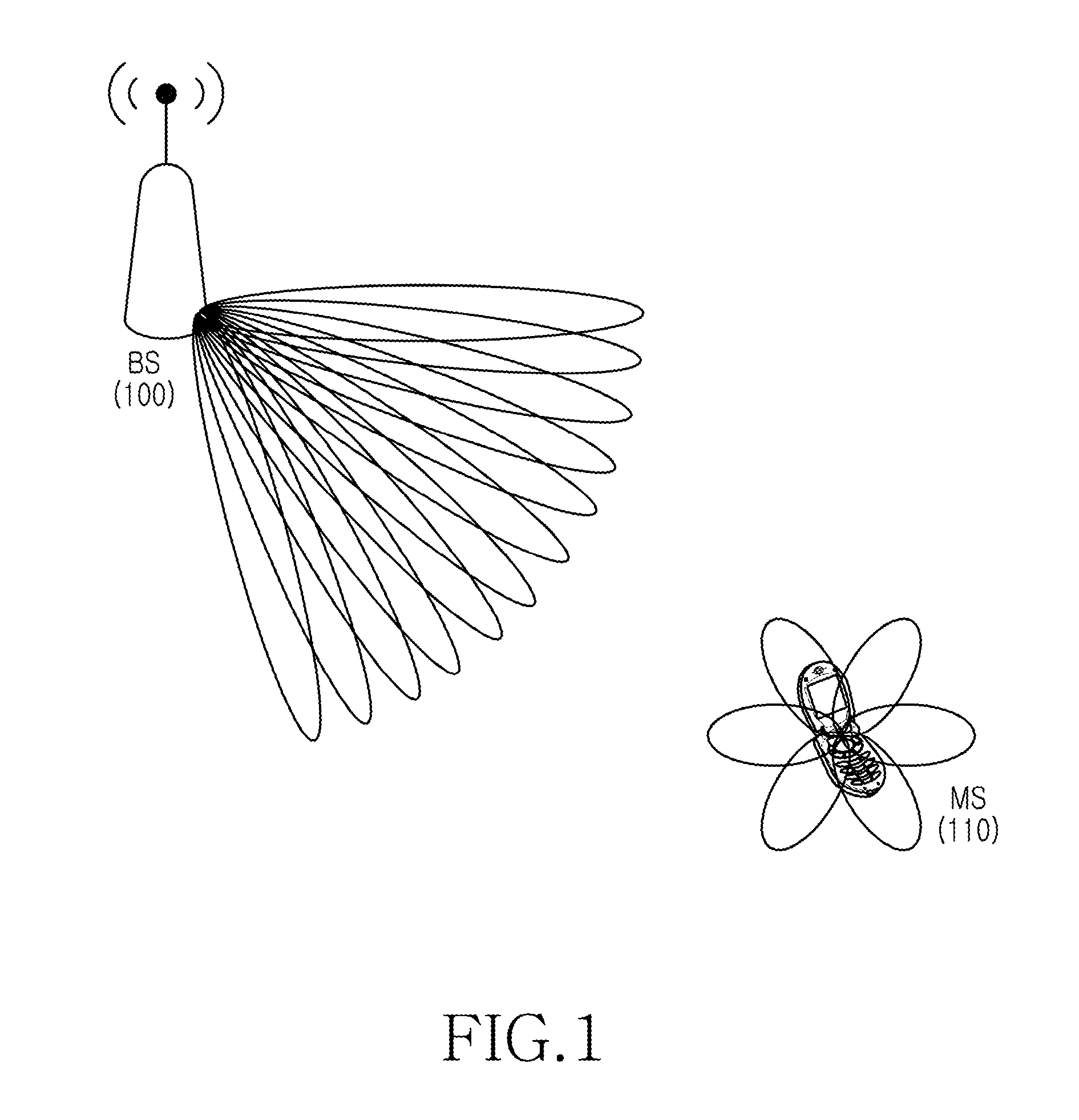
When supporting the wireless communication over the UHF band, the wireless communication system is subject to increasing propagation losses such as path loss or return loss, due to frequency properties of the frequency band.

Method used


Image

  • Apparatus and method for beam selecting in beamformed wireless communication system
  • Apparatus and method for beam selecting in beamformed wireless communication system
  • Apparatus and method for beam selecting in beamformed wireless communication system

Examples


Embodiment Construction

[0036]The following description with reference to the accompanying drawings is provided to assist in a comprehensive understanding of exemplary embodiments of the invention as defined by the claims and their equivalents. It includes various specific details to assist in that understanding but these are to be regarded as merely exemplary. Accordingly, those of ordinary skill in the art will recognize that various changes and modifications of the embodiments described herein can be made without departing from the scope and spirit of the invention. In addition, descriptions of well-known functions and constructions may be omitted for clarity and conciseness.

[0037]The terms and words used in the following description and claims are not limited to the bibliographical meanings, but, are merely used by the inventor to enable a clear and consistent understanding of the invention. Accordingly, it should be apparent to those skilled in the art that the following description of exemplary embod...


PUM


Abstract

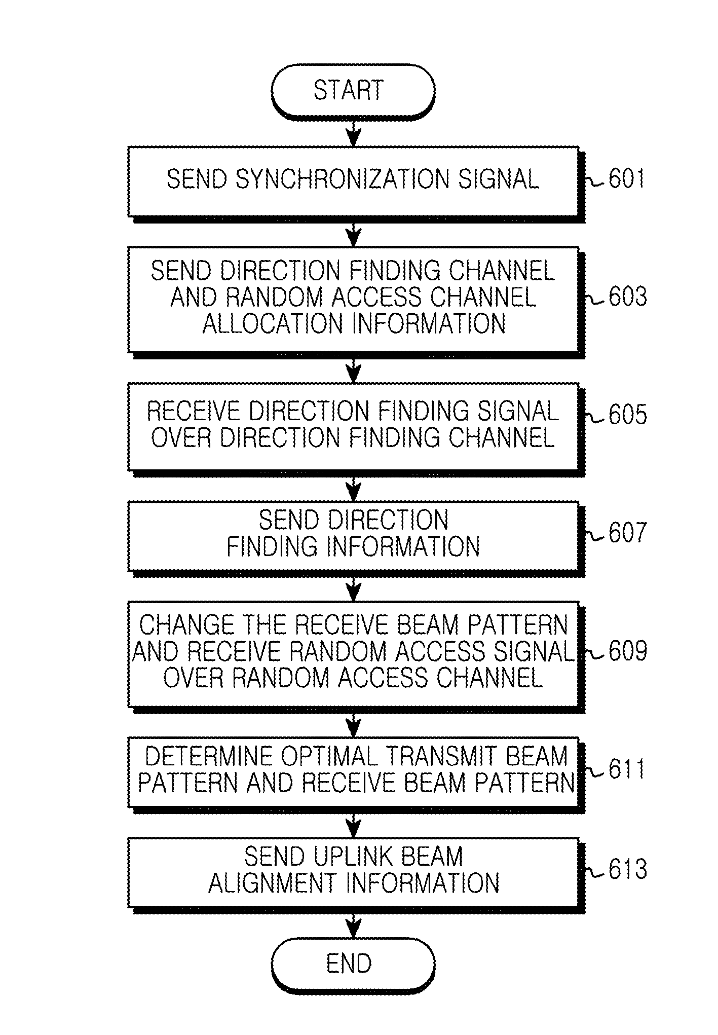
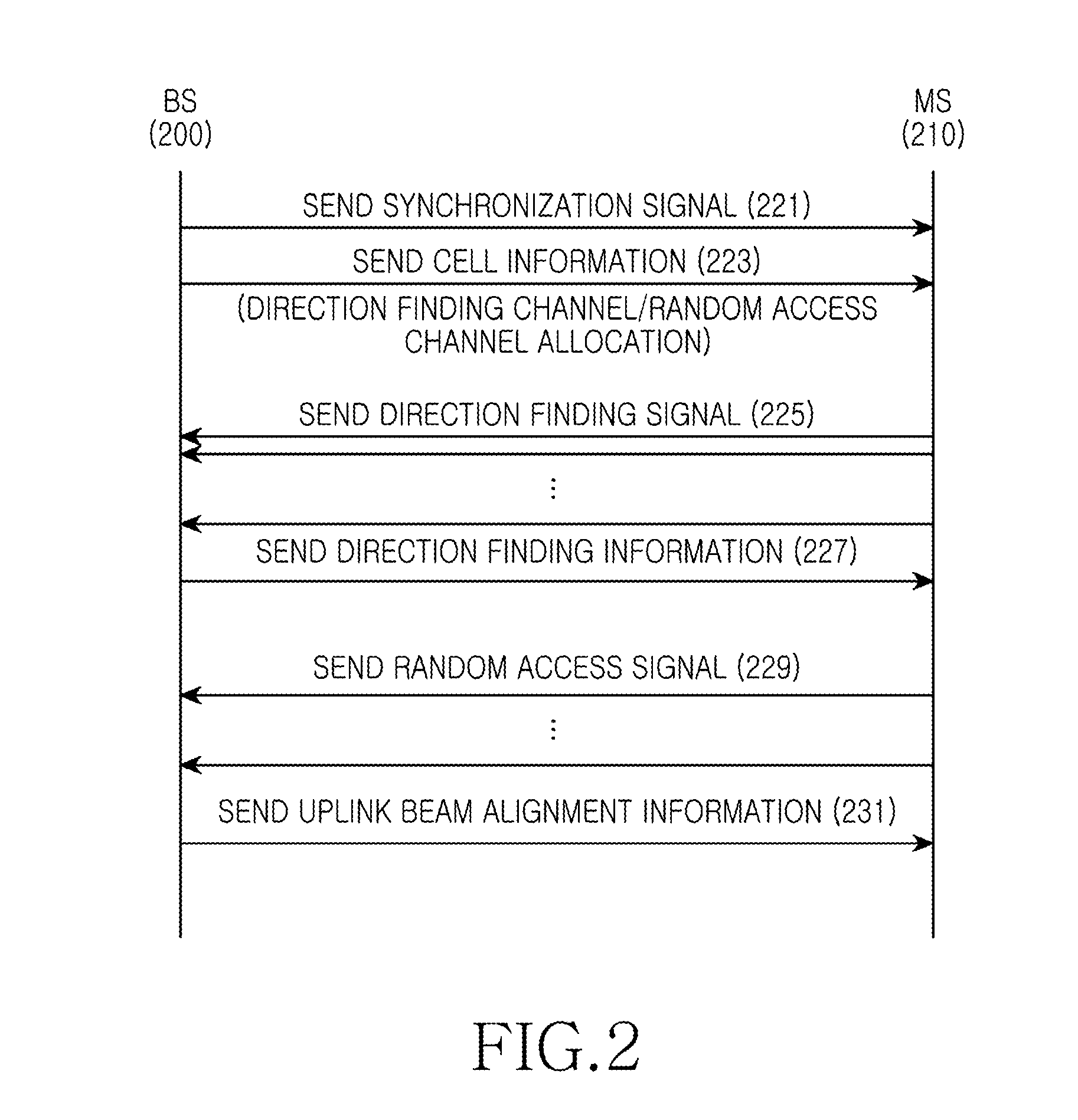
An apparatus and a method for reducing delay during beam alignment in a beamformed wireless communication system are provided. A method for selecting a beam pattern in a Base Station (BS) includes determining whether a direction finding signal is received through each time interval of a direction finding channel, transmitting information of whether the direction finding signal is received with respect to each time interval of the direction finding channel, changing a receive beam pattern and receiving a random access signal from a Mobile Station (MS) with at least one transmit beam pattern over a random access channel, and selecting one of transmit beam patterns of the MS and one of receive beam patterns of the BS according to the random access signal.

Description

PRIORITY[0001]This application claims the benefit under 35 U.S.C. §119(a) of a Korean patent application filed on Sep. 15, 2011 in the Korean Intellectual Property Office and assigned Serial No. 10-2011-0092906 and a Korean patent application filed on Sep. 14, 2012 in the Korean Intellectual Property Office and assigned Serial No. 10-2012-0102020, the entire disclosures of which are hereby incorporated by reference.BACKGROUND OF THE INVENTION[0002]1. Field of the Invention[0003]The present invention relates to a beamformed wireless communication system. More particularly, the present invention relates to an apparatus and a method for uplink beam alignment for initial access of a mobile station in a beamformed wireless communication system.[0004]2. Description of the Related Art[0005]To meet wireless data traffic demand continuously increasing, wireless communication systems are advancing for supporting a high data rate. For example, to increase the data rate, the wireless communicat...

Claims


Application Information

Patent Timeline
Patent Type & Authority Applications(United States)
IPC IPC(8): H04W72/00H04W72/04
CPCH04B7/0617H04B7/0695H04B7/086H04W74/008H04W72/042H04W72/046H04B7/088H04B7/063H04W72/23H04W74/002H04B7/0408H04B7/0413
Inventor JEONG, SU-RYONGKIM, TAE-YOUNGLIM, CHI-WOOYU, HYUN-KYU
Owner SAMSUNG ELECTRONICS CO LTD
Learn More