Eureka AIR delivers breakthrough ideas for toughest innovation challenges, trusted by R&D personnel around the world.

Area soil moisture and fertilization sensor

Inactive Publication Date: 2013-03-21
VIDOVICH DENNIS
View PDF13 Cites 2 Cited by
  • Summary
  • Abstract
  • Description
  • Claims
  • Application Information

AI Technical Summary

Benefits of technology

The present invention provides a method and system for controlled irrigation and fertilization that eliminates the need for adjustments by using memo-rized soil conductance values as reference values for subsequent cycles. This simplifies the process and improves efficiency.

Problems solved by technology

The limited resource availability necessitates use of controlled irrigation in soil fields.
However, sprinkler and flood irrigation along with mass spraying, besides being wasteful of water and chemical resources, often damage the surface soils and both ground water and surface water sources.
Flood irrigation also creates large swings over time in the amount of moisture in the soil, which stresses the plants.
Furthermore, in traditional flood irrigation a significant percentage of water applied to the field is lost either through evaporation to the air or downward migration below the effective root zone of the plants.
The downward migration of water also has the negative consequence of carrying fertilizers, pesticides and insecticides into the groundwater.
This technique wastes water resources, as does the more advanced sprinkler techniques, although to a lesser extent.
They have had limited success, because they tend to measure the absolute soil moisture level.
The main problem with such device is that soil conditions can significantly modify the readings.
They do not provide the grower with any direct analysis presentation that fit individual needs of his own crop in terms of water and fertilizer application at a given point in time.
Thus, traditional irrigation and fertilization methods are very wasteful of resources and are not focused on plant production and have a harsh impact on the environment.

Method used


Image

  • Area soil moisture and fertilization sensor
  • Area soil moisture and fertilization sensor
  • Area soil moisture and fertilization sensor

Examples


Embodiment Construction

[0024]In the following detailed description of embodiments of the invention, numerous specific details are set forth in order to provide a thorough understanding of the embodiment of the invention. However, it will be obvious to a person skilled in art that the embodiments of invention may be practiced with or without these specific details. In other instances well known methods, procedures and components have not been described in details so as not to unnecessarily obscure aspects of the embodiments of the invention.

[0025]Furthermore, it will be clear that the invention is not limited to these embodiments only. Numerous modifications, changes, variations, substitutions and equivalents will be apparent to those skilled in the art, without parting from the spirit and scope of the invention.

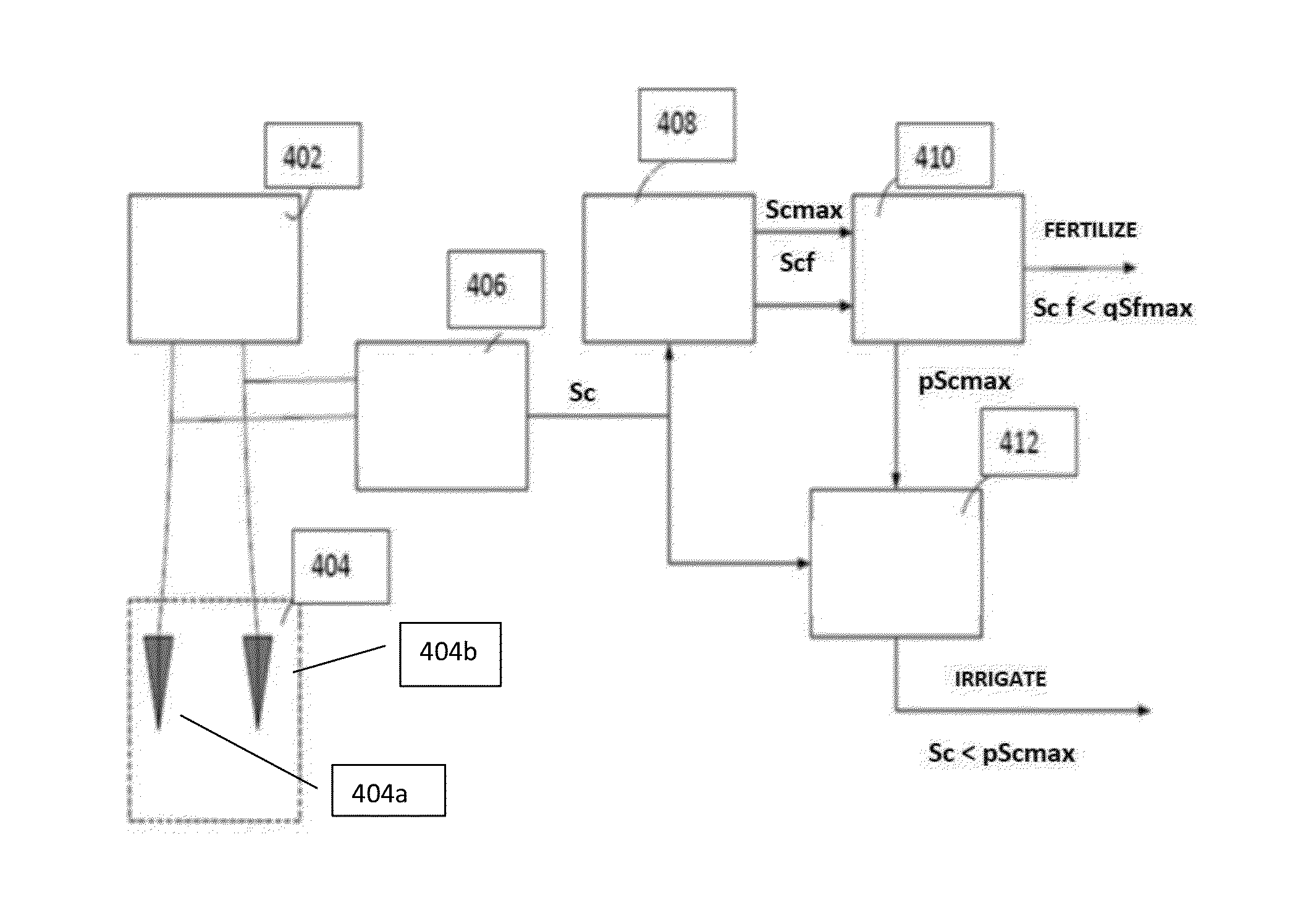
[0026]The present invention relates to a method and a system for simultaneously operating irrigation and fertilization in a vast area that includes more than thousand square feet. An electric field...


PUM


Abstract

The present invention relates to a method and a system for irrigation and fertilization control in a vast area, based on measuring the soil resistive electrical conductance values, during watering and fertilization cycles. A continuous electric field is created below the subsurface of the large soil area by a device that is spaced many feet apart in order to propagate an electric field through the soil. This alternating electric field averages soil conductance and therefore eliminates effects of non-uniformity in a monitored area. Furthermore, absolute conductance variations over long time periods offer the accurate point in time for soil fertilization.

Description

FIELD OF THE INVENTION[0001]The present invention relates to irrigation and a fertilization control system. More particularly, the present invention provides a method and a system for delivering adequate amount of water and fertilizer to a vast area.BACKGROUND OF THE INVENTION[0002]World's limited water resource is one of the primary reasons for restricted agriculture production in many areas. The limited resource availability necessitates use of controlled irrigation in soil fields. Efficient use of water and fertilizer are important components of sustainable green house production and improved crop productivity.[0003]Irrigation or watering systems are well known in the art. Conventional growing practices often utilize sprinkler and flood-type irrigation techniques to irrigate the agricultural fields. In addition, mass spraying of chemicals is used for fumigating and fertilizing the agricultural fields.[0004]Sprinkler systems are the devices with perforations, through which water i...

Claims


Application Information

Patent Timeline
IPC IPC(8): A01G25/16
CPCA01G25/167
Inventor VIDOVICH, NIKOLA V.
Owner VIDOVICH DENNIS
Why Eureka
Eureka Blog
Learn More