Cooling system and method for operating a cooling system

Active Publication Date: 2013-03-28
AIRBUS OPERATIONS GMBH
View PDF17 Cites 5 Cited by
  • Summary
  • Abstract
  • Description
  • Claims
  • Application Information

AI Technical Summary

Benefits of technology

[0030]The flow line may comprise a cooling line branch, in which the at least one cooling station is arranged, and a bypass branch connected in parallel with the cooling line branch, the cooling line branch and the bypass branch leading into the return line. The refrigerant can thus be led past the cooling station without having to flow through the cooling station. A bypass control valve may be adapted to control the flow of the refrigerant through the cooling line branch and/or the bypass branch. This enables a cold running of the components of the cooling circuit outside the region in which the cooling station is arranged. This is useful particularly on the transition of the cooling system from its rest state to the normal operation when at least parts of the cooling circuit are heated up and a partial evaporation of the liquid refrigerant is to be feared. By control of the bypass valve, the refrigerant can be led past the cooling station until the refrigerant is sufficiently supercooled. Subsequently, by appropriate

Problems solved by technology

Furthermore, by using a cooling system with a central refrigerating device arranged outside the passenger cabin it is possible to avoid machine noises generated by refrigerating units placed in the region of the transport container locations, which noises are audible in the aircraft passenger cabin and hence may be found to be disturbing.
A problem that is posed by the cooling system disclosed in DE 10 2006 005 035 B3 is, however, the high rest pressure of the refrigerant that may arise in the

Method used


Image

  • Cooling system and method for operating a cooling system
  • Cooling system and method for operating a cooling system
  • Cooling system and method for operating a cooling system

Examples


first embodiment

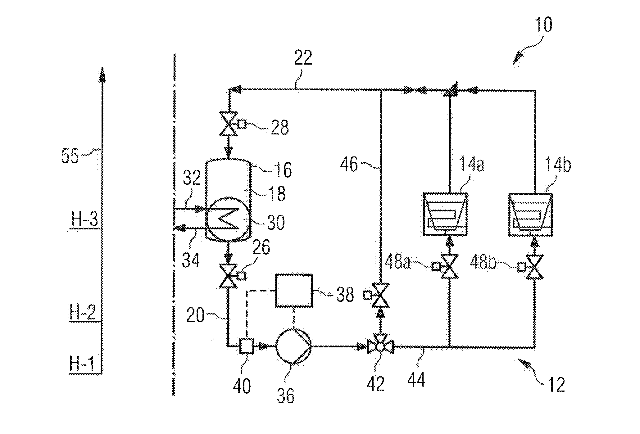
[0045]FIG. 1 shows a cooling system 10 which is suitable in particular for cooling food on board an aircraft. The cooling system 10 comprises a cooling circuit 12 which supplies cooling energy to two cooling stations 14a and 14b. A refrigerant circulates in the cooling circuit 12. Arrows mark the flow direction of the refrigerant in the cooling circuit 12. The refrigerant is converted from the liquid to the gaseous state of aggregation on releasing its cooling energy to the cooling stations 14a, 14b and subsequently converted back to the liquid state of aggregation again by appropriate pressure and temperature control in the cooling circuit 12. The cooling stations 14a, 14b thus have the function of an evaporator and constitute the interface between the cooling circuit 12 and a system to be cooled.

[0046]The cooling system 10 further comprises a refrigerant container 16 which comprises a receiving space 18 arranged in an interior space of the refrigerant container for receiving the r...

second embodiment

[0076]a cooling system 10 illustrated in FIG. 2 differs from the arrangement according to FIG. 1 merely in that the cooling system 10 has a refrigerating device 50. The further refrigerant is in this case formed as liquid refrigerant and the cooling circuit in the refrigerating device 50 is operated without phase change. In this case, the first heat exchanger line 32 is connected to the outlet of a refrigerating machine 52. The second heat exchanger line 34 is connected to the inlet of the refrigerating machine 52.

[0077]The refrigerating device 50 further comprises a pump 54 for conveying the further refrigerant in the direction of the refrigerating machine 52. The cooling circuit in which the further refrigerant circulates may comprise, in addition to the components shown in FIG. 2, also further components, such as control valves, valves or equalising tanks. Preferably, the pipelines of the refrigerating device 50 illustrated in FIG. 2 are of such a short design that it is possible...
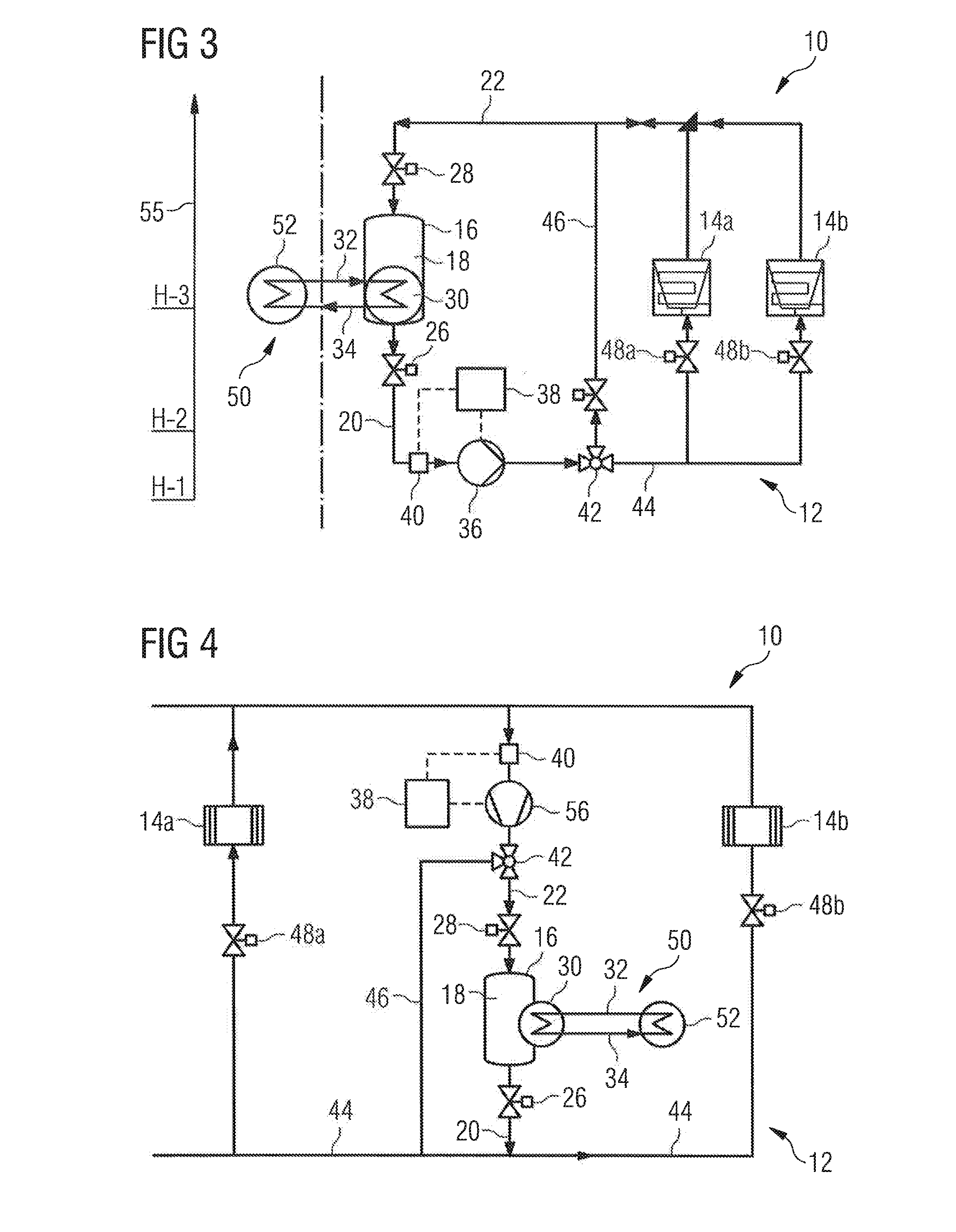
third embodiment

[0078]a cooling system 10 illustrated in FIG. 3 differs from the arrangement according to FIG. 1 only in that the cooling system has a refrigerating device 50. The further refrigerant is in this case formed as a two-phase refrigerant, as is the refrigerant. The refrigerating machine 52 of the refrigerating device 50 is directly connected to the heat exchanger 30 via the first and the second heat exchanger line 32, 34. A pump can be dispensed with, thereby enabling a weight and volume reduction.

[0079]Alongside the cooling system 10 in FIGS. 1 to 3 can be seen a qualitative height scale 55, which gives an indication of the height at which the components of the cooling system 10 are located when the cooling system 10 is installed in the aircraft. H-1 represents a low height, H-2 represents a medium height and H-3 represents a great height above a lowest point of the underside of the aircraft. Owing to the height arrangements of the individual components of the cooling system 10 illustr...


PUM


Abstract

A cooling system for cooling food on board an aircraft includes a cooling circuit adapted to supply cooling energy to at least one cooling station, a refrigerant circulating in the cooling circuit selected such that it is convertible at least partially from the liquid to the gaseous state of aggregation on releasing its cooling energy to the at least one cooling station and subsequently convertible back at least partially to the liquid state of aggregation again by an appropriate pressure and temperature control in the cooling circuit, and a refrigerant container including a receiving space arranged in an interior space of the refrigerant container which receives the refrigerant circulating in the cooling circuit, the receiving space of the refrigerant container connected to the cooling circuit by a flow line for discharging the refrigerant from the receiving space and by a return line for returning the refrigerant into the receiving space.

Description

TECHNICAL FIELD[0001]The invention relates to a cooling system which is designed in particular for operation with a two-phase refrigerant and is suitable for cooling food on board an aircraft. Furthermore, the invention relates to a method for operating such a cooling systemBACKGROUND OF RELATED ART[0002]A cooling system suitable for operation with a two-phase refrigerant is known from DE 10 2006 005 035 B3 and is used for example to cool food which is stored on board a passenger aircraft and intended to be distributed to the passengers. Typically, the food intended for supplying to the passengers is kept in mobile transport containers. These transport containers are filled and precooled outside the aircraft and after loading into the aircraft are placed at appropriate locations in the aircraft passenger cabin, for example in the galleys. In order to guarantee that the food remains fresh up to being distributed to the passengers, in the region of the transport container locations co...

Claims


Application Information

Patent Timeline
IPC IPC(8): F25B41/00F25B1/00
CPCF25B23/006F25B1/00Y02B30/745F25B2600/13F25B41/00Y02B30/70
Inventor PIESKER, MARKUSKIRYAMAN, AHMET KAYIHANROERING, SEBASTIAN
Owner AIRBUS OPERATIONS GMBH
Why Eureka
Try Eureka