Dielectric barrier discharge wind tunnel

a technology of dielectric barrier and wind tunnel, which is applied in the direction of instruments, plasma techniques, structure/machine measurement, etc., can solve the problems of wind tunnels that are not suitable for low-speed flow characterization or small-scale structure testing, unsteady fluid flow, and disturbances affecting flow characterization, so as to reduce boundary layer separation, reduce pressure loss, and smoke flow

Inactive Publication Date: 2013-03-28
UNIV OF FLORIDA RES FOUNDATION INC
View PDF3 Cites 12 Cited by
  • Summary
  • Abstract
  • Description
  • Claims
  • Application Information

AI Technical Summary

Benefits of technology

[0003]Embodiments of the subject invention are directed to a method and apparatus for inducing fluid flow in a wind tunnel using one or more plasma actuators. In an embodiment, a wind tunnel is provided having a flow passage. A pair of electrodes is positioned on at least one surface of the flow passage, and a voltage potential is applied across the pair of electrodes producing a plasma discharge in the flow passage. The pair of electrodes can be positioned such that when the plasma discharge is produced an electrohydrodynamic (EHD) body force is generated that induces flow of a fluid in the flow passage.
[0004]In an embodiment, a testing chamber is positioned in the flow passage and the EHD body force generated tends to induce flow of the fluid toward the testing chamber. In an embodiment, a subject to be tested is positioned in the flow passage and the EHD body force generated tends to induce flow of the fluid toward the subject. In an embodiment, the pair of electrodes is positioned such that the EHD body force generated tends to reduce a shear force on a surface of the flow passage. In another embodiment, the pair of electrodes is positioned at or near a corner of the flow passage such that EHD body force generated tends to redirect flow around the corner. The EHD body force generated can result in a smoother flow, decreased pressure loss, and / or reduced boundary layer separation. In a further embodiment, the pair of electrodes is positioned such that the EHD body force generated tends to contract or defuse flow of the fluid. In yet another embodiment, the pair of electrodes is positioned at or near an inlet of the flow passage and the EHD body force generated tends to direct flow of the fluid into the inlet. In yet another embodiment, the pair of electrodes is positioned at or near an outlet of the flow passage and the EHD body force generated tends to direct flow of the fluid out of the outlet. The EHD body force generated can tend to induce laminar flow in the fluid. In another embodiment, the EHD body force generated tends to induce turbulent flow in the fluid. In other embodiments, the EHD body force generated is used to otherwise control the flow of the fluid in the flow passage.
[0005]Various configurations of electrodes can be used with various embodiments of the subject invention. A pair of electrodes can be positioned on one of the at least one surface of the flow passage. In an embodiment, the surface incorporates an insulating material, an exposed electrode of the pair of electrodes is exposed to an inside of the flow passage, and an embedded electrode of the pair of electrodes is separated from the exposed electrode by the insulating material such that when the pair of electrodes is powered a surface discharge is produced. In another embodiment, a pair of electrodes is positioned across at least a portion of the flow passage such that when the pair of electrodes is powered a volumetric discharge is produced. Additional pairs of electrodes can be positioned in the flow passage and powered to produce additional plasma discharges. In an embodiment, three or more electrodes are positioned in the flow passage and powered in phased pairs. In yet another embodiment, one or more multi-barrier plasma actuators are utilized. The embodiments presented here are illustrative examples. Various other configurations can be used with the subject invention.

Problems solved by technology

Challenges in traditional wind tunnels include disturbances that affect the flow characterization at all speed regimes.
This is especially problematic at low and moderate speeds where vibration from a blower or fan at off-design points can introduce unsteadiness in the fluid flow.
While there are arc discharge plasma wind tunnels for high speed applications, such wind tunnels are not suitable for low speed flow characterization or testing of small structures.

Method used


Image

  • Dielectric barrier discharge wind tunnel
  • Dielectric barrier discharge wind tunnel
  • Dielectric barrier discharge wind tunnel

Examples


Embodiment Construction

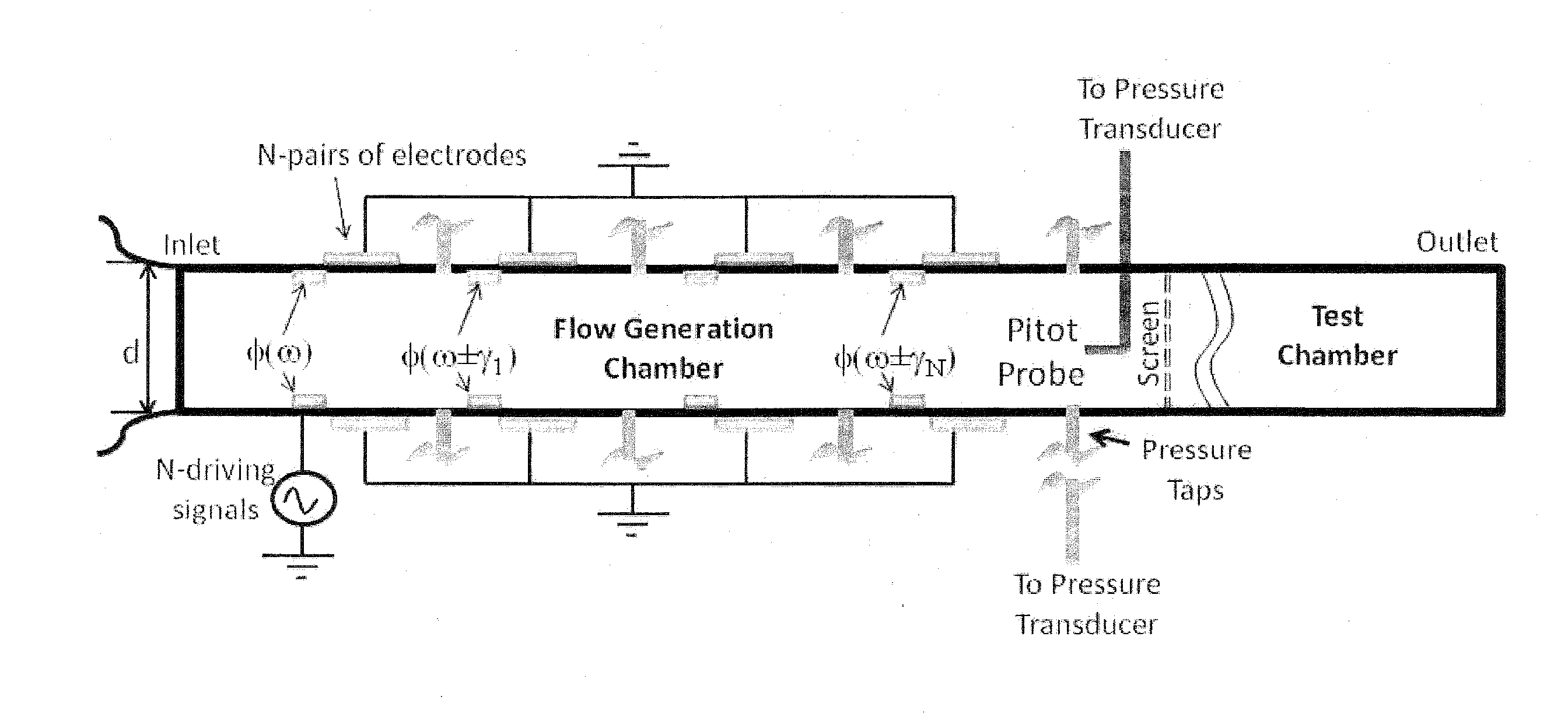
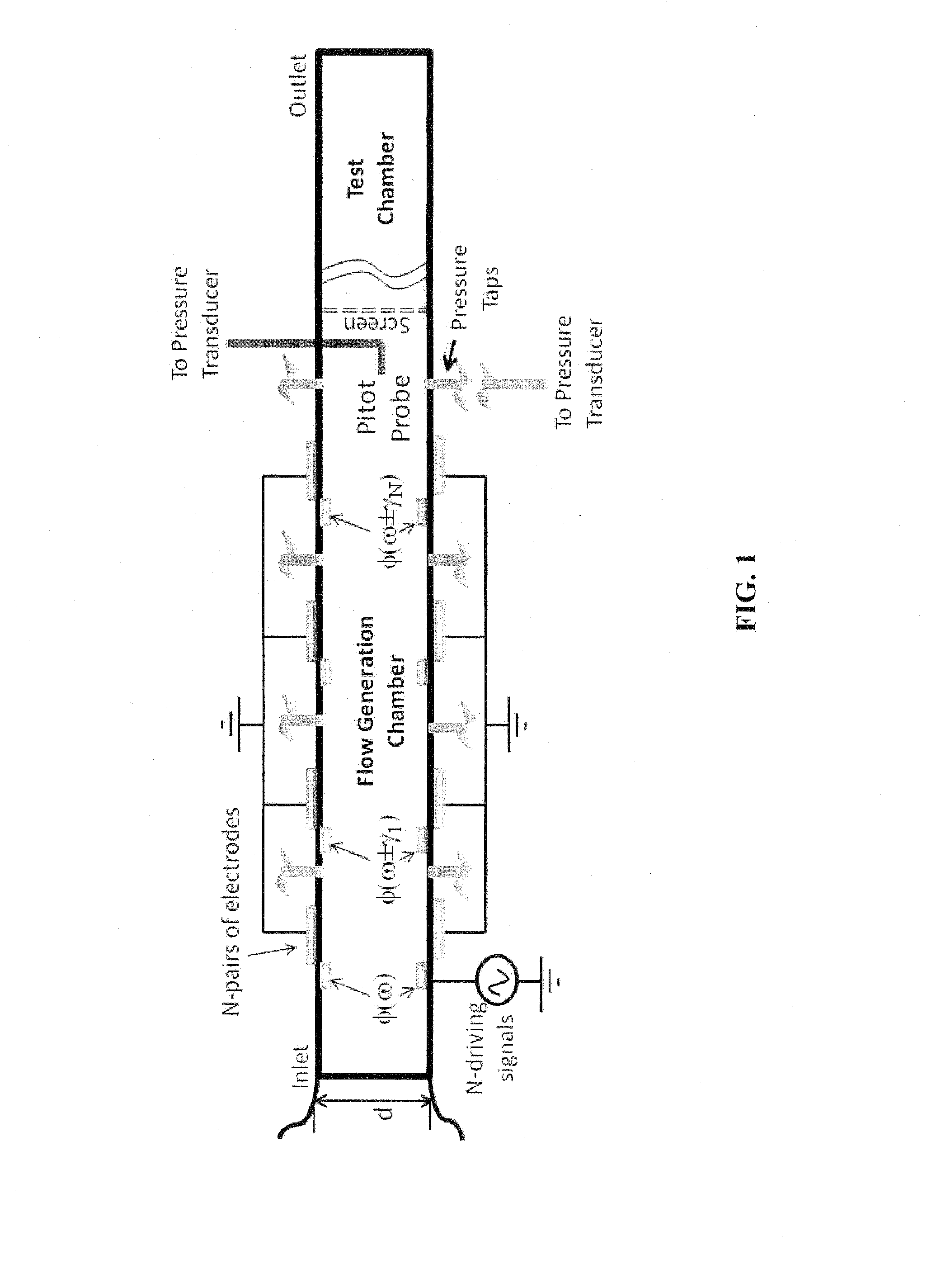
[0037]Embodiments of the subject invention are directed to a method and apparatus for inducing fluid flow in a wind tunnel using one or more plasma actuators. In an embodiment, a wind tunnel is provided that uses one or more plasma actuators to induce fluid flow in a flow passage. In an embodiment, less mechanical vibration is created than in a traditional wind tunnel employing a blower or fan. In a further embodiment, plasma actuators are used to augment the fluid flow induced by a blower or fan. In a specific embodiment, a wind tunnel is produced having no rotating or mechanical components, such as a solid state wind tunnel.

[0038]In an embodiment, a plasma actuator of the one or more plasma actuators incorporates at least one pair of electrodes positioned on one or more surfaces of the flow passage. When a voltage potential is applied across one of the at least one pair of electrodes a plasma discharge is produced that induces fluid flow in the flow passage. In an embodiment, when...


PUM


Abstract

Embodiments of the subject invention are directed to methods and apparatus for inducing fluid flow in a wind tunnel using one or more plasma actuators. In an embodiment, a wind tunnel is provided having a flow passage. A pair of electrodes is positioned on at least one surface of the flow passage, and a voltage potential is applied across the pair of electrodes producing a plasma discharge in the flow passage. In an embodiment, the pair of electrodes is positioned on the at least one surface of the flow passage such that when the plasma discharge is produced an electrohydrodynamic (EHD) body force is generated that induces flow of a fluid in the flow passage.

Description

[0001]The subject invention was made with government support under Air Force Office of Scientific Research, Contract No. FA9550-09-1-0416. The government has certain rights to this invention.BACKGROUND OF INVENTION[0002]Challenges in traditional wind tunnels include disturbances that affect the flow characterization at all speed regimes. This is especially problematic at low and moderate speeds where vibration from a blower or fan at off-design points can introduce unsteadiness in the fluid flow. While there are arc discharge plasma wind tunnels for high speed applications, such wind tunnels are not suitable for low speed flow characterization or testing of small structures.BRIEF SUMMARY[0003]Embodiments of the subject invention are directed to a method and apparatus for inducing fluid flow in a wind tunnel using one or more plasma actuators. In an embodiment, a wind tunnel is provided having a flow passage. A pair of electrodes is positioned on at least one surface of the flow pass...

Claims


Application Information

Patent Timeline
Patent Type & Authority Applications(United States)
IPC IPC(8): H05B1/00
CPCG01M9/04H05H1/2406H05B1/00H05H2001/245H05H2001/2456H05H2001/2437H05H1/2437H05H1/246H05H1/245H05H1/2439
Inventor ROY, SUBRATA
Owner UNIV OF FLORIDA RES FOUNDATION INC
Why Eureka
Try Eureka