
Composite charged particle beam apparatus

Active Publication Date: 2013-03-28
HITACHI HIGH TECH SCI CORP
View PDF4 Cites 9 Cited by
  • Summary
  • Abstract
  • Description
  • Claims
  • Application Information

AI Technical Summary

Benefits of technology

The present invention is a composite charged particle beam apparatus that has two charged particle beams arranged perpendicular to each other. This apparatus allows for easy adjustment of a sample stage while observing the focused ion beam or electron beam through an observation image. The position of the sample can be adjusted without causing malfunctions due to incorrect operation. The technical effect of this invention is good operability of the composite charged particle beam apparatus.

Problems solved by technology

Therefore, the composite charged particle beam apparatus in which two beams are orthogonally arranged has a problem in that an erroneous operation is apt to occur when an operator adjusts a processing observation position of the sample while looking at the observation image of the focused ion beam or the electron beam.

Method used


Image

  • Composite charged particle beam apparatus
  • Composite charged particle beam apparatus
  • Composite charged particle beam apparatus

Examples

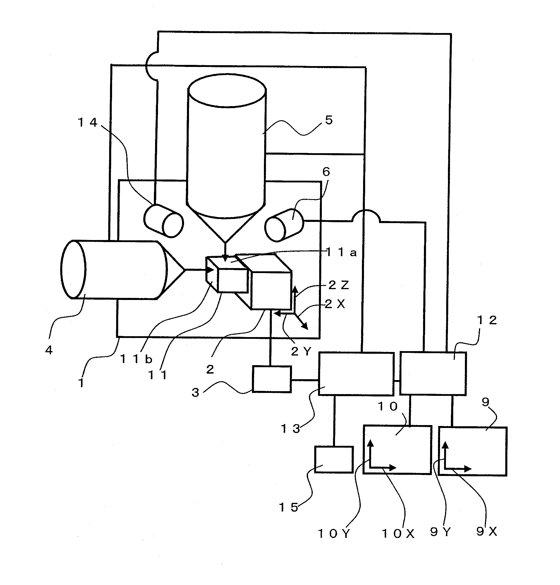
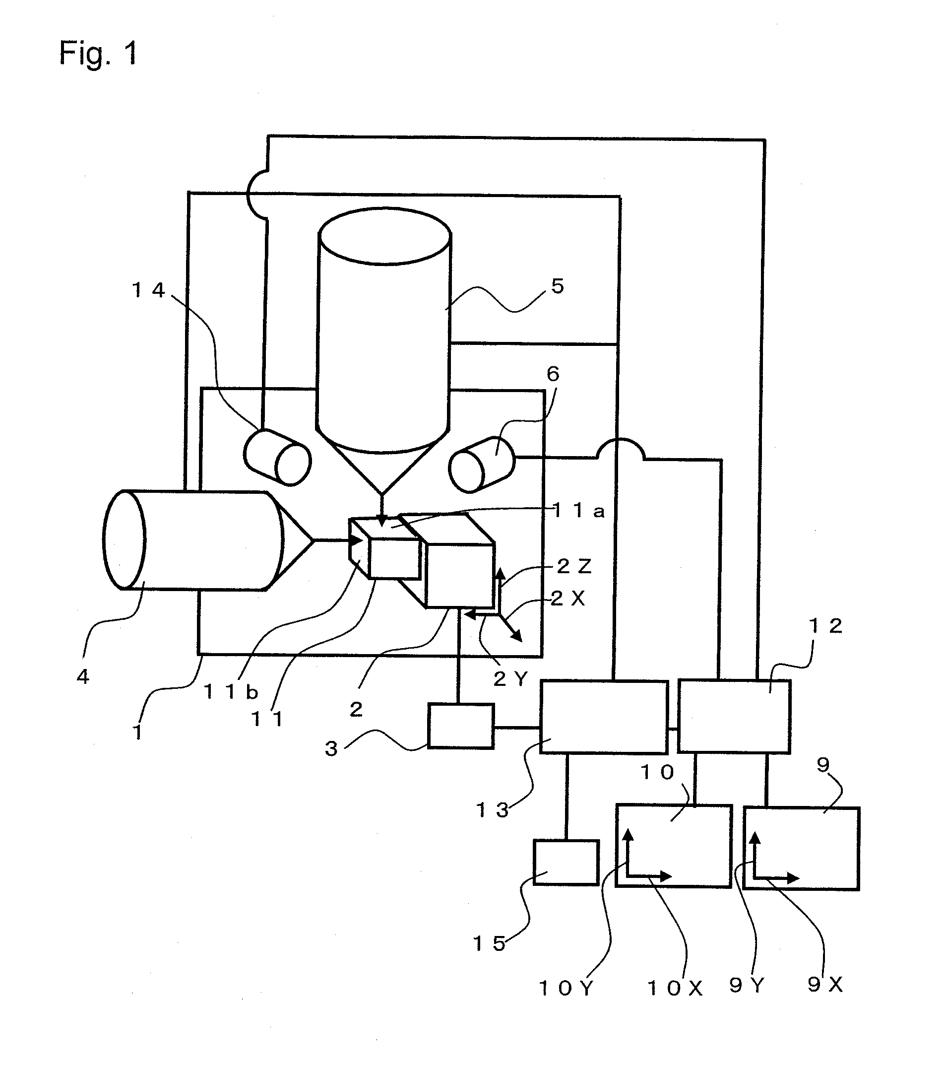

Embodiment Construction

[0025]Now, a composite charged particle beam apparatus according to an embodiment of the present invention is described.

[0026]As illustrated in FIG. 1, the composite charged particle beam apparatus of this embodiment includes a sample stage 2 for moving a sample 11 in a sample chamber 1. The composite charged particle beam apparatus further includes an electron beam column 5 for irradiating the sample 11 with an electron beam and a focused ion beam column 4 for irradiating the sample 11 with a focused ion beam. The electron beam column 5 and the focused ion beam column 4 are arranged so that beam irradiation axes thereof may intersect with each other substantially perpendicularly.

[0027]Particles generated from the sample 11 through the irradiation of the focused ion beam or the electron beam are detected by a detector 6, and the acquired particles are subjected to time-series processing by an image formation portion 12, thereby forming an observation image. Note that, the particles ...


PUM


Abstract

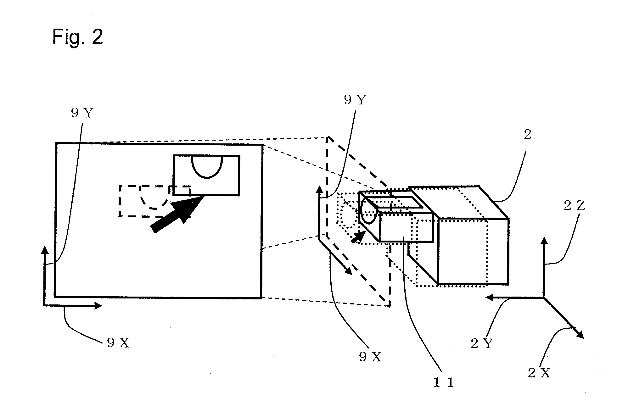
Provided is a composite charged particle beam apparatus, including: a focused ion beam column (4); an electron beam column (6) orthogonal to the focused ion beam column (4); a sample stage (2) for moving a sample (11); an optical microscope (14) for observing the sample (11); a display portion (12, 13) capable of displaying a focused ion beam image, an electron beam image, and an optical microscope image, and a stage control portion (3) for moving the sample stage (2) in accordance with a coordinate system of each image.

Description

BACKGROUND OF THE INVENTION[0001]1. Field of the Invention[0002]The present invention relates to a composite charged particle beam apparatus for observing a sample subjected to processing by a focused ion beam through a charged particle microscope.[0003]2. Description of the Related Art[0004]A focused ion beam apparatus is used for observation of a processed cross-section of a sample, production of a sample for transmission electron microscope observation, and other such purposes. Particularly in a composite charged particle beam apparatus including an electron beam apparatus, a cross-section which is under processing by a focused ion beam or a cross-section which has been processed by the focused ion beam can be observed in-situ by an electron beam. Such a composite charged particle beam apparatus is therefore widely used for successive cross-section observation and successive sample production.[0005]In a general composite charged particle beam apparatus, the focused ion beam and t...

Claims


Application Information

Patent Timeline
IPC IPC(8): H01J37/26
CPCH01J37/261G01N23/2208G01N23/225G01N1/32G01N2223/0816H01J2237/31749G01N2223/105H01J37/28H01J37/317H01J2237/20285H01J2237/31745G01N2223/102
Inventor UEMOTO, ATSUSHIYAMAMOTO, YOASAHATA, TATSUYA
Owner HITACHI HIGH TECH SCI CORP
Learn More