Mid-voltage variable-frequency driving system and total harmonic distortion compensation control method

a variable frequency driving system and total harmonic distortion compensation technology, applied in the direction of dynamo-electric converter control, motor/generator/converter stopper, ac network to reduce harmonics/ripples, etc., can solve the problem of dead zones of conventional three-phase switch-mode rectifier modules, high cost and complex design,

Active Publication Date: 2013-03-28
DELTA ELECTRONICS SHANGHAI CO LTD
View PDF6 Cites 27 Cited by
  • Summary
  • Abstract
  • Description
  • Claims
  • Application Information

AI Technical Summary

Benefits of technology

[0055]Another aspect of this invention is to provide a total harmonic distortion compensation control method for a mid-voltage variable-frequency driving system. The mid-voltage variable-frequency driving system includes a three-phase switch-mode rectifier module, a three-phase electrical grid, a controller and a total harmonic distortion compensation unit. The three-phase switch-mode rectifier module is coupled to the three-phase electrical grid. The controller is coupled with the three-phase switch-mode rectifier module. The total harmonic distortion compensation unit is coupled to the controller. The total harmonic distortion compensation control method includes: inputting an initial reactive component reference value into the total harmonic distortion compensation unit, wherein t

Problems solved by technology

In the controlling of an electric-driven machine or an induction motor, it is an important issue to adjust a motor speed.
A conventional electric-driven machine adopts a DC speed regulating technique, and the applications thereof are limited applications due to big volume and high failure rate of hardware.
However, the multistage transformer arranged in the aforementioned conventional mid-voltage variable-frequency speed-regulating system is of large volume and high weight, thus leading to high cost and complex design.
Thus, it is an important research issue regarding how to use other speed-regulating system structures to omit the arrangement of the transformer while the same performance is achieved.
However, it is still an issue desired to be solved that a conventional three-phase switch-mode rectifier module has dead zones.
Thus, the zone of the phase angle difference can be considered as

Method used


Image

  • Mid-voltage variable-frequency driving system and total harmonic distortion compensation control method
  • Mid-voltage variable-frequency driving system and total harmonic distortion compensation control method
  • Mid-voltage variable-frequency driving system and total harmonic distortion compensation control method

Examples


Embodiment Construction

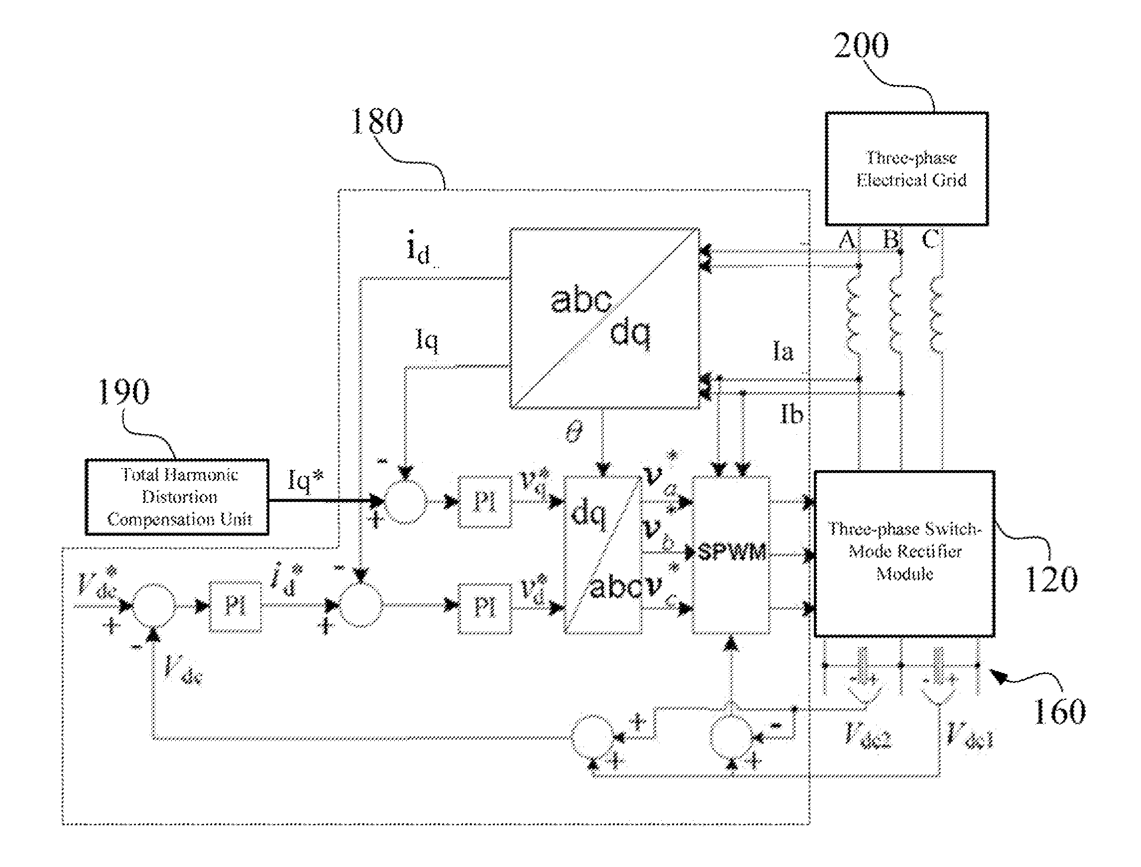
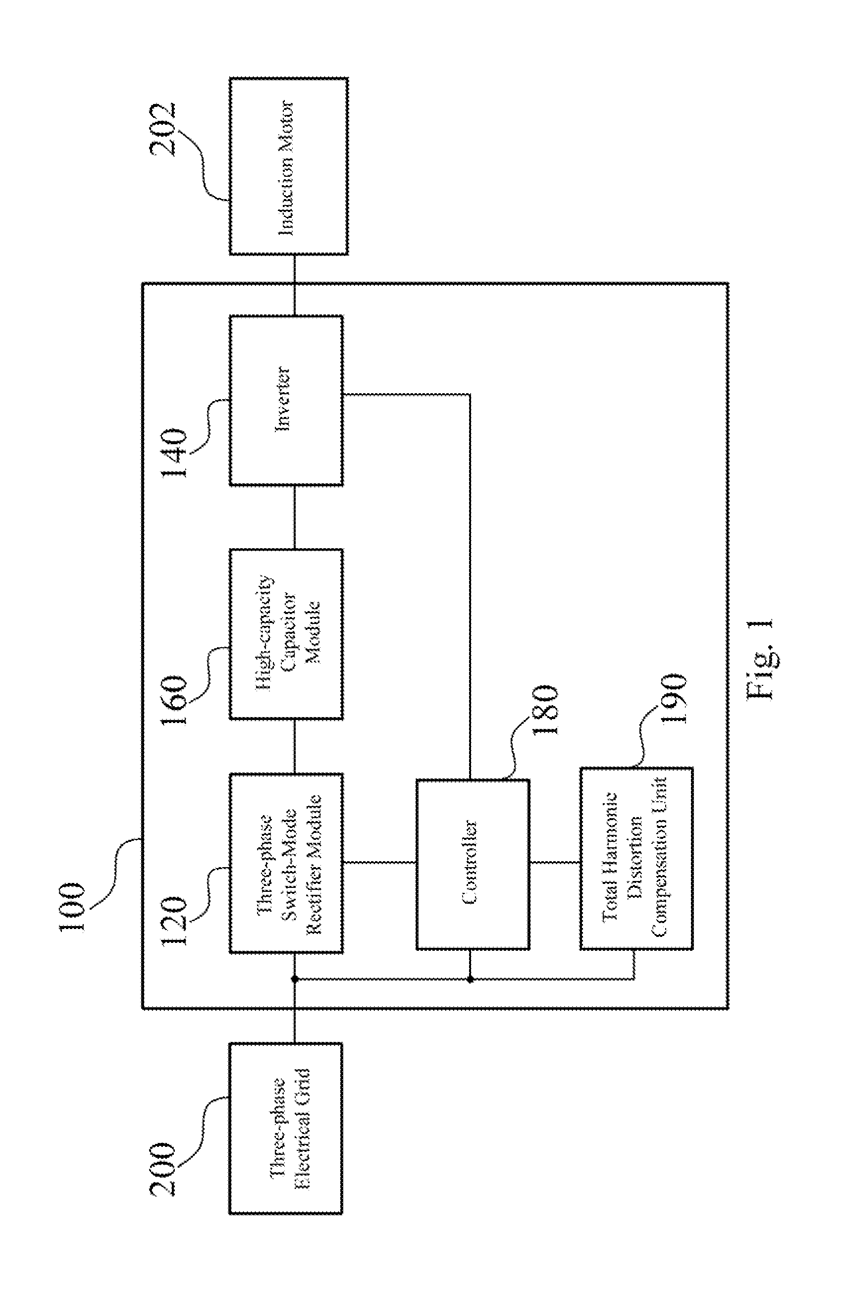
[0071]Referring to FIG. 1, FIG. 1 illustrates a schematic functional block diagram of a mid-voltage variable-frequency driving system 100 according to an embodiment of this invention. In practical application, the mid-voltage variable-frequency driving system 100 is coupled to a three-phase electrical grid 200, and can be used for driving an induction motor 202. As shown in FIG. 1, the mid-voltage variable-frequency driving system 100 includes a three-phase switch-mode rectifier module 120, an inverter 140, a high-capacity capacitor module 160, a controller 180 and a total harmonic distortion (THD) compensation unit 190.

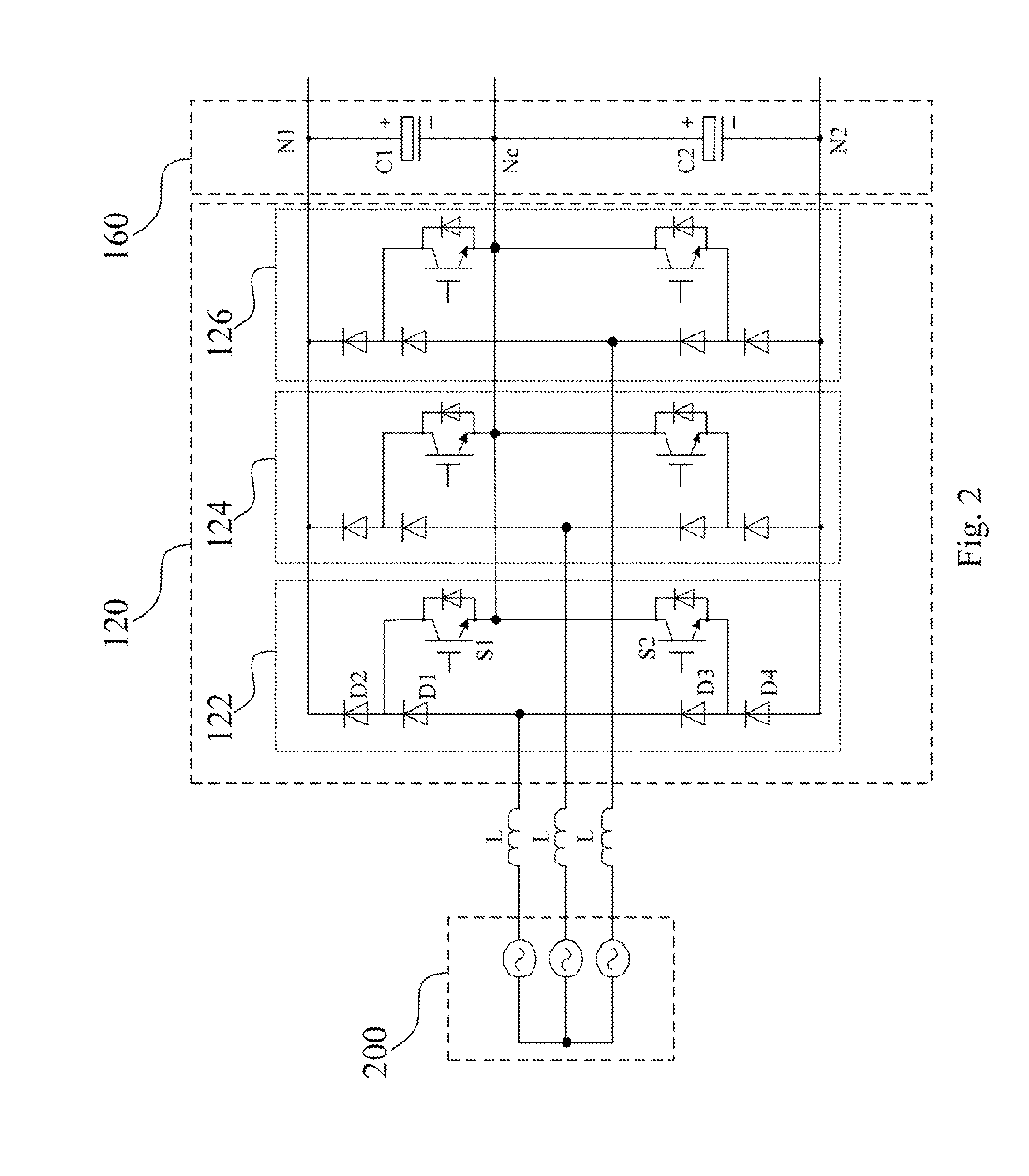
[0072]The three-phase switch-mode rectifier module 120 is coupled to the three-phase electrical grid 200 for converting an AC voltage input with a fixed operating frequency on the three-phase electrical grid 200 into a DC voltage. The inverter 140 is coupled to the three-phase switch-mode rectifier module 120. The inverter 140 is combined with the three-phase switch-...


PUM


Abstract

A mid-voltage variable-frequency driving system and a total harmonic distortion compensation control method are provided in this invention. The mid-voltage variable-frequency driving system includes a total harmonic distortion compensation unit. The total harmonic distortion compensation unit is used to perform an optimal adjustment on a reactive component reference value of a grid-side phase current, such that a harmonic component of the grid-side phase current may be reduced and a power factor of a three-phase switch-mode rectifier module within the mid-voltage variable-frequency driving system may be maintained.

Description

RELATED APPLICATIONS[0001]This application claims priorities to Chinese Application Serial Number 201110286981.7, filed Sep. 23, 2011, and Chinese Application Serial Number 201110348824.4, filed Nov. 7, 2011 which are herein incorporated by references.BACKGROUND[0002]1. Field of Invention[0003]This invention relates to a rectifier module. More particularly, this invention relates to a distortion compensation control method available for a three-phase switch-mode rectifier module with a current mono-direction.[0004]2. Description of Related Art[0005]In the controlling of an electric-driven machine or an induction motor, it is an important issue to adjust a motor speed. A conventional electric-driven machine adopts a DC speed regulating technique, and the applications thereof are limited applications due to big volume and high failure rate of hardware.[0006]A variable-frequency drive (VFD) is an electric driving element using the variable-frequency technology and the microelectronic t...

Claims


Application Information

Patent Timeline
IPC IPC(8): H02P29/00H02M7/155
CPCH02J3/01Y02E40/40Y02E40/30H02J3/18H02P27/08
Inventor CHEN, WEIPU, BO-YUZHANG, YI
Owner DELTA ELECTRONICS SHANGHAI CO LTD
Why Eureka
Try Eureka