Liquid crystal display device and liquid crystal lens

a liquid crystal display and display device technology, applied in the field of liquid crystal display devices and liquid crystal lens, can solve the problems of difficult to ensure a sufficient mechanical strength, difficult to maintain and difficult to ensure the mechanical strength of display devices using liquid crystal lenses, etc., to achieve the effect of increasing the mechanical strength of the liquid crystal display device and maintaining the effect of liquid crystal lens

Active Publication Date: 2013-03-28
JAPAN DISPLAY INC
View PDF4 Cites 21 Cited by
  • Summary
  • Abstract
  • Description
  • Claims
  • Application Information

AI Technical Summary

Benefits of technology

[0017]According to the present invention, the thickness of the upper substrate of the liquid crystal lens is made larger than the thickness of the lower substrate. Thus, it is possible to increase the mechanical strength of the liquid crystal display device and to stably maintain the liquid crystal lens effect.
[0018]According to another aspect of the present invention, in addition to the above effect, the liquid crystal layer of the liquid crystal lens can be protected against ultraviolet light, because a protective film that blocks ultraviolet light with a wavelength of 340 nm or shorter is bonded onto the upper substrate via a bonding material for protective film.

Problems solved by technology

If the thicknesses of the liquid crystal display panel and the liquid crystal lens are reduced, it is difficult to ensure a sufficient mechanical strength even if these layers are laminated.
A liquid crystal display device using a liquid crystal lens is especially prone to be influenced by mechanical strength, because weak mechanical strength influences both a gap variation in the liquid crystal display panel and a gap variation in the liquid crystal lens.
In particular, the liquid crystal lens is susceptible to external stress, because it is situated outward and its liquid crystal layer has a larger thickness.

Method used


Image

  • Liquid crystal display device and liquid crystal lens
  • Liquid crystal display device and liquid crystal lens
  • Liquid crystal display device and liquid crystal lens

Examples


first example

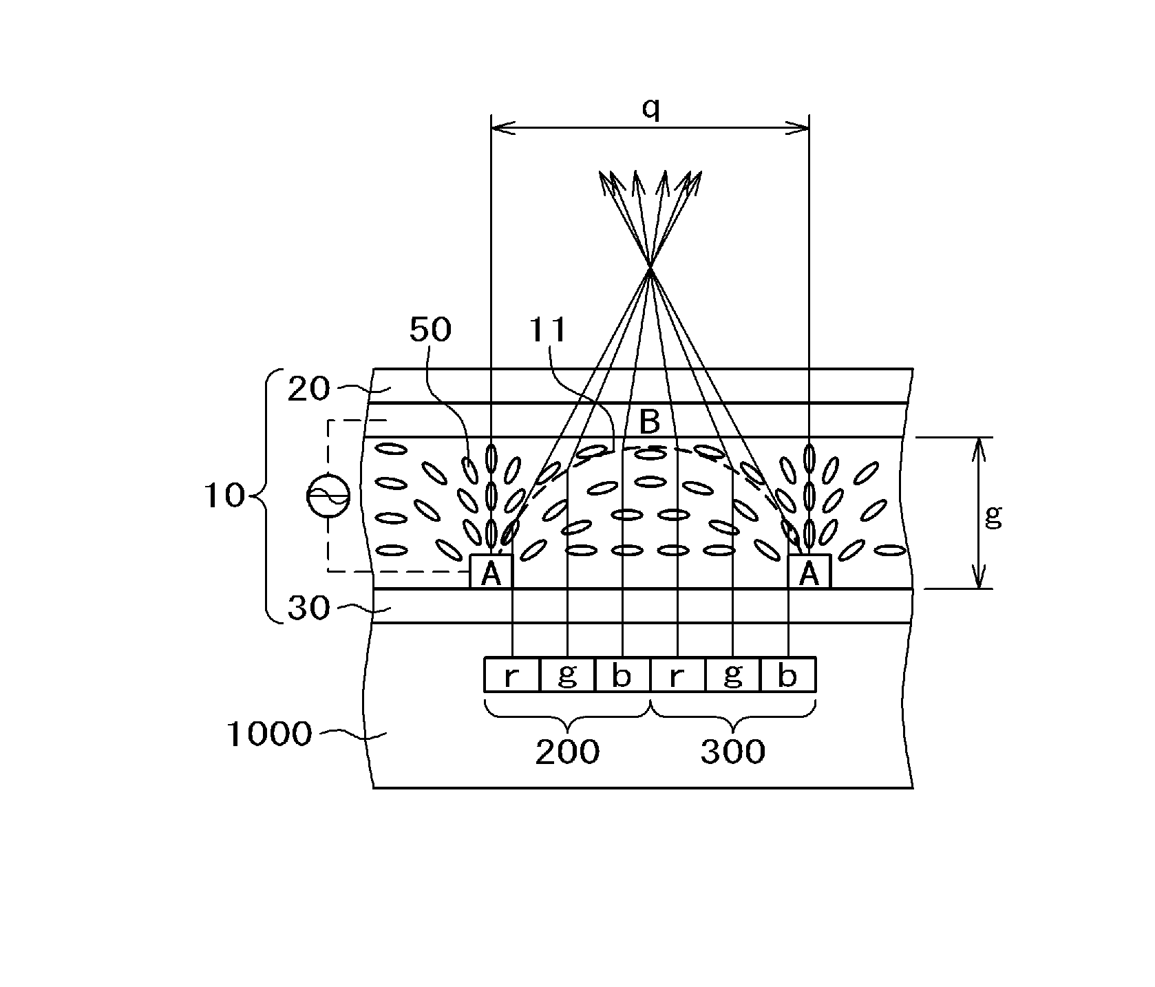
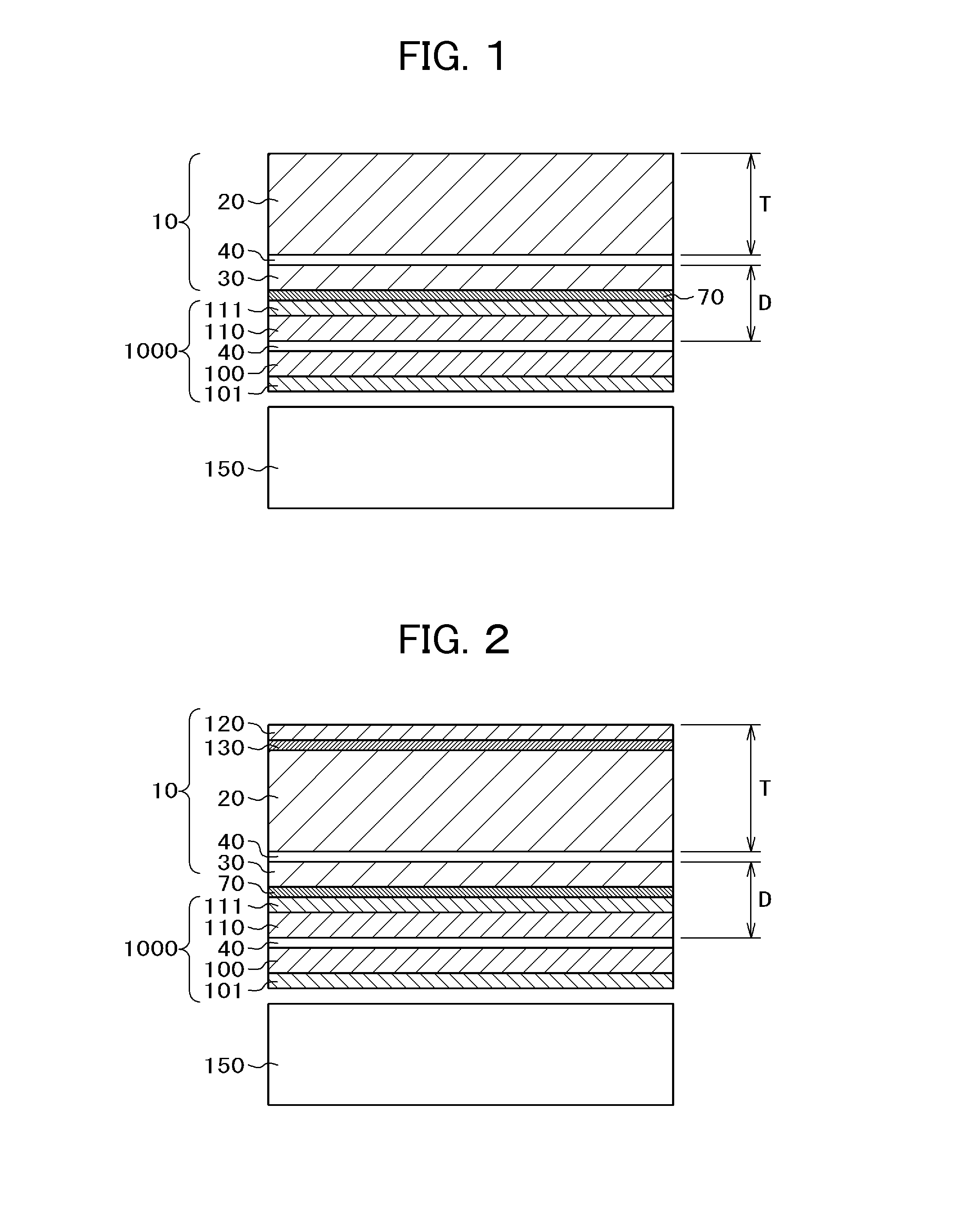
[0034]FIG. 1 is a cross-sectional diagram of a liquid crystal display device including the liquid crystal lens 10 of First Example. In the present specification, a device including the liquid crystal lens 10, the liquid crystal display panel 1000, and a backlight 150 is referred to as a liquid crystal display device. In FIG. 1, the liquid crystal display panel 1000 is disposed on the top of the backlight 150 and the liquid crystal lens 10 is bonded onto the upper surface of the liquid crystal display panel 1000 with a bonding material 70. The backlight 150 in FIG. 1 is, for example, comprised of an LED light source, a light guide plate, a reflective sheet bonded onto the underside of the light guide plate, optical sheets such as a diffusion sheet and a prism sheet placed between the light guide plate and the liquid crystal display panel, and so forth.

[0035]The liquid crystal display panel 1000 has a structure in which a liquid crystal layer 40 is sandwiched between a TFT substrate10...

second example

[0044]FIG. 2 is a cross-sectional diagram of a liquid crystal display device to illustrate Second Example of the present invention. In FIG. 2, the backlight 150, the liquid crystal display panel 1000, and the liquid crystal lens 10 up to the upper substrate 20 are the same as in FIG. 1 for First Example. The present example differs from First Example shown in FIG. 1 in that a protective film 120 is bonded onto the upper surface of the upper substrate 20 of the liquid crystal lens 10 via a bonding material for film 130. The thickness of the protective film 120 is approximately 0.1 mm and the thickness of the boding material 130 is approximately 0.025 mm. In this way, by bonding the protective film 120 onto the upper substrate 20 of the liquid crystal lens 10 via the bonding material for protective film 130, shattering of glass or the like is avoided even in case the upper substrate 20 has broken due to the effect of the bonding material 130.

[0045]In the case of the liquid crystal dis...


PUM

PropertyMeasurementUnit
thicknessaaaaaaaaaa
wavelengthaaaaaaaaaa
refractive indexaaaaaaaaaa

Abstract

In a liquid crystal display device enabling three-dimensional display using a liquid crystal lens, both mechanical strength and a liquid crystal lens effect are satisfied. The liquid crystal lens is bonded onto an upper polarizing plate of a liquid crystal display panel with a bonding material. The liquid crystal lens includes an upper substrate, a lower substrate and a liquid crystal layer sandwiched therebetween. The upper substrate of liquid crystal lens has a thickness larger than a total of the thickness of the lower substrate of the liquid crystal lens and the thickness of the liquid crystal display panel. Thereby, it is possible to realize a liquid crystal display device satisfying both the mechanical strength and liquid crystal lens effect.

Description

CLAIM OF PRIORITY[0001]The present application claims priority from Japanese Patent Application JP 2011-206778 filed on Sep. 22, 2011, the content of which is hereby incorporated by reference into this application.FIELD OF THE INVENTION[0002]The present invention relates to a display device and a liquid crystal display device that enables three-dimensional display by using a liquid crystal lens.BACKGROUND OF THE INVENTION[0003]In a liquid crystal display panel, a display region is formed such that a TFT substrate over which pixel electrodes and thin-film transistors (TFTs), inter alia, are formed in a matrix and an opposing substrate over which color filters, inter alia, are formed in positions corresponding to the pixel electrodes in the TFT substrate are placed facing each other and liquid crystals are sandwiched between the TFT substrate and the opposing substrate. An image is produced by controlling light transmissibility through liquid crystal molecules pixel by pixel. Since li...

Claims


Application Information

Patent Timeline
Patent Type & Authority Applications(United States)
IPC IPC(8): G02F1/1335G02B30/25
CPCG02B3/14G02F1/1335
Inventor YAMAZAKI, HIROYUKIISHII, SAKAEKOBAYASHI, SETSUO
Owner JAPAN DISPLAY INC
Why Eureka
Try Eureka