Power factor correction (PFC) circuit configured to control high pulse load current and inrush current

a technology of power factor correction and inrush current, which is applied in the direction of power conversion systems, climate sustainability, efficient power electronics conversion, etc., can solve the problems of high storage device requirements, high loss in dc-dc converters at a lower load, and damage to circuitries across application instruments

Active Publication Date: 2013-03-28
GENERAL ELECTRIC CO
View PDF15 Cites 44 Cited by
  • Summary
  • Abstract
  • Description
  • Claims
  • Application Information

AI Technical Summary

Benefits of technology

[0006]In accordance with one embodiment of the invention, a power circuit for protecting against high pulse load current and inrush current is disclosed. The power circuit comprises a buck-boost module and a PFC controller operatively coupled with the buck-boost module. The PFC controller is configured to receive an input voltage feedback, an output voltage feedback, and a current feedback, and is further configured to utilize one of an Integral Gain Compensation (IGC) and an Integral Value Compensation (IVC) to control the high pulse load current and inrush current in the power circuit.
[0007]In accordance with another embodiment of the invention, a method for controlling high pulse load current and inrush current in a power circuit is disclosed. The method comprises receiving an input voltage feedback, receiving an output voltage feedback, and receiving a current feedback. Further, the method comprises utilizing one of an Integral Gain Compensation (IGC) and Integral Value Compensation (IVC) for managing operations of the power circuit in order to control the high pulse load current and the inrush current in the power circuit instantaneously.
[0008]In accordance with yet another embodiment of the invention, a method utilizing one of an Integral Gain Compensation (IGC) and Integral Value Compensation (IVC) techniques for controlling charging / loading current at a value for ensuring no output disturbances is disclosed. The method comprises determining a load value and a load flag value, providing a slope of an output voltage feedback and manipulating values of load and time. Additionally, the method comprises compensating required input alternating current instantaneously for a given pulse load by utilizing one of the Integral Value compensation and the Integral gain compensation, providing a boost flag, where the boost flag indicates a mode of operation, and calculating the current limiting constant, and producing a rectified scaled down sinusoidal waveform. Further, the method comprises multiplying an output from the voltage error amplifier with the current limiting constant, providing output to control a duty cycle, and controlling inductor current values by changing the current limiting constant for controlling charging / loading current at a value for ensuring no output disturbances.

Problems solved by technology

Such inrush current is undesirable, and may cause damage to circuitries across application instruments, such as, a mobile or portable radiographic X-ray machine.
However, this technique has a high storage device requirement, since the output voltage control has to be slow to maintain PFC and there is restriction on output voltage for stable operation of the boost converter.
Further, as the load range is very high in high power mobile radiographic X-ray application, the loss in the DC-DC converter is very high at a lower load because of a high DC bus voltage value.

Method used


Image

  • Power factor correction (PFC) circuit configured to control high pulse load current and inrush current
  • Power factor correction (PFC) circuit configured to control high pulse load current and inrush current
  • Power factor correction (PFC) circuit configured to control high pulse load current and inrush current

Examples


Embodiment Construction

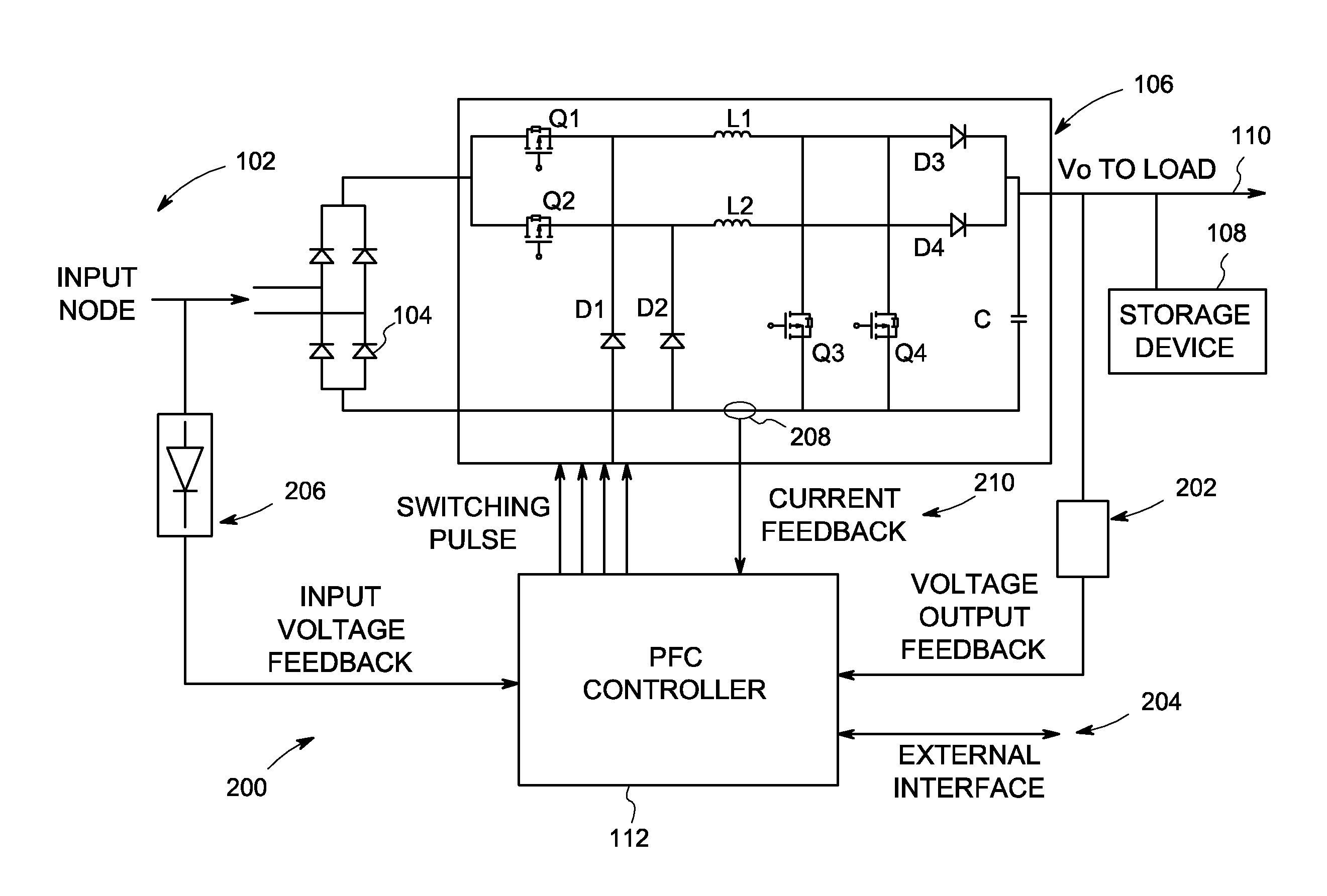
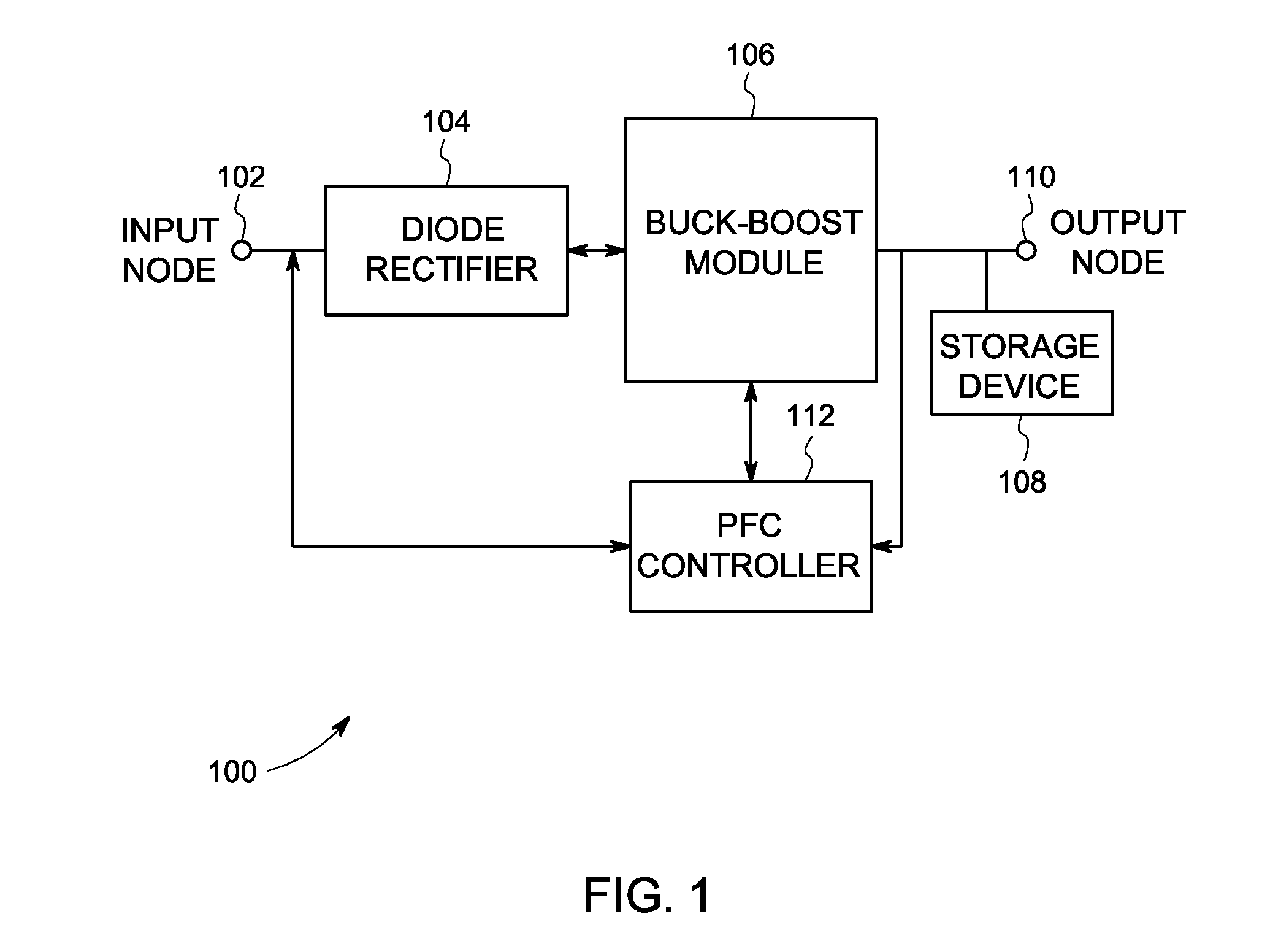
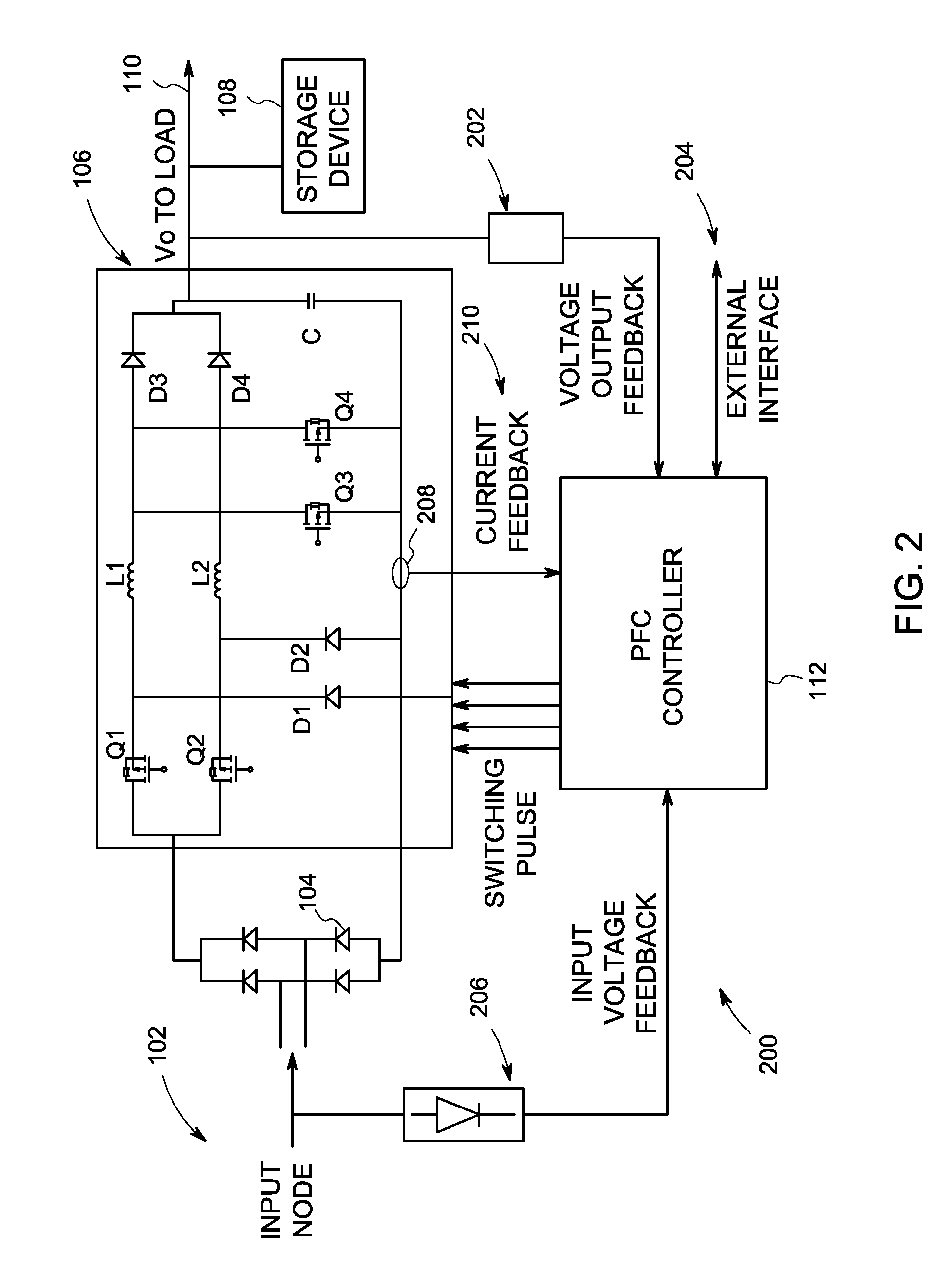
[0025]Various embodiments of the present invention provide an efficient, compact, cost effective and stable power factor correction (PFC) converter circuit. PFC converter circuits are utilized in several applications including mobile and portable radiographic X-ray machines that can be operated from a standard wall socket (e.g. conditions in which the maximum current available is limited). Specifically, embodiments provide a novel scheme to control inrush current at a specified level of ramp slope and peak current during start-up, to control the line current instantaneously for pulse load, and to control the output DC bus voltage. A single pulse width modulation (PWM) and control loop with different compensation techniques i.e. ‘Integral Gain Compensation (IGC) and Integral Value Compensation (IVC)’ are used in embodiments of the present invention to do the above functions. Embodiments of the present invention utilize ‘buck switches’ and ‘freewheeling diodes’ in addition to a normal...


PUM


Abstract

A power circuit for protecting against high pulse load current and inrush current is disclosed. The power circuit comprises a buck-boost module and a PFC controller operatively coupled with the buck-boost module. The PFC controller is configured to receive an input voltage feedback, an output voltage feedback, and a current feedback, and is configured to utilize one of an Integral Gain Compensation (IGC) and an Integral Value Compensation (IVC) to control the high pulse load current and inrush current in the power circuit.

Description

BACKGROUND OF THE INVENTION[0001]Embodiments of the present invention relate generally to current control techniques and overload protection circuits and, more particularly to a power factor correction (PFC) circuit configured to control high pulse load current and inrush current.[0002]PFC circuits utilize various protection means against high pulse load current and inrush current. The inrush current is an initial high current flow, usually a short duration surge, usually attributable to a highly reactive initial power load. Such inrush current is undesirable, and may cause damage to circuitries across application instruments, such as, a mobile or portable radiographic X-ray machine.[0003]Various circuits and techniques have been used in the past to control high pulse load current and inrush current. For example, one such conventional technique utilizes a power factor controller using a boost converter. However, this technique has a high storage device requirement, since the output ...

Claims


Application Information

Patent Timeline
Patent Type & Authority Applications(United States)
IPC IPC(8): H02M1/36
CPCH02M1/4225Y02B70/126H02M7/125Y02B70/10
Inventor KUMAR, NIRANJAN
Owner GENERAL ELECTRIC CO
Why Eureka
Try Eureka