Drill head for a deep hole drilling tool for bta deep hole drilling, and deep hole drilling tool

a drilling tool and drill head technology, applied in drilling tools, boring/drilling equipment, turning apparatus, etc., can solve the problems of increased tool investment and productivity losses, adverse effects on costs, and insufficient tool life of known bta deep hole drilling tools or drill heads of these bta deep hole drilling tools, etc., to achieve easy exchange and easy setting of defined variation in spacing.

Inactive Publication Date: 2013-03-28
TBT TIEFBOHRTECHN
View PDF40 Cites 14 Cited by
  • Summary
  • Abstract
  • Description
  • Claims
  • Application Information

AI Technical Summary

Benefits of technology

[0014]An object of the invention is to provide a generic BTA / STS or ejector deep hole drilling head which makes it possible to have a high tool life during the machining of the most diverse possible materials and which tends to a lesser extent to oscillate during the drilling operation. Furthermore, an object of the invention is to provide a corresponding BTA deep hole drilling tool.

Problems solved by technology

It became apparent, however, that the known BTA deep hole drilling tools or the drill heads of these BTA deep hole drilling tools do not have sufficient tool lives and / or do not deliver sufficient borehole quality during the machining of some materials, as compared to other materials.
In particular, the circular-ground chamfer on the secondary cutting edge, which chamfer forms with the two guide pads the three-point bearing contact, is severely loaded during the BTA deep hole drilling of these materials, and therefore the cutting edge has to be exchanged at an early stage, this having an adverse effect upon costs.
Short tool lives signify frequent tool change and therefore increased tool investment and productivity losses.
Moreover, it was shown that, in the machining of some materials, the known BTA deep hole drilling tools tend to oscillate during the deep hole drilling operation, and this may likewise have an adverse effect upon borehole quality.

Method used


Image

  • Drill head for a deep hole drilling tool for bta deep hole drilling, and deep hole drilling tool
  • Drill head for a deep hole drilling tool for bta deep hole drilling, and deep hole drilling tool
  • Drill head for a deep hole drilling tool for bta deep hole drilling, and deep hole drilling tool

Examples


Embodiment Construction

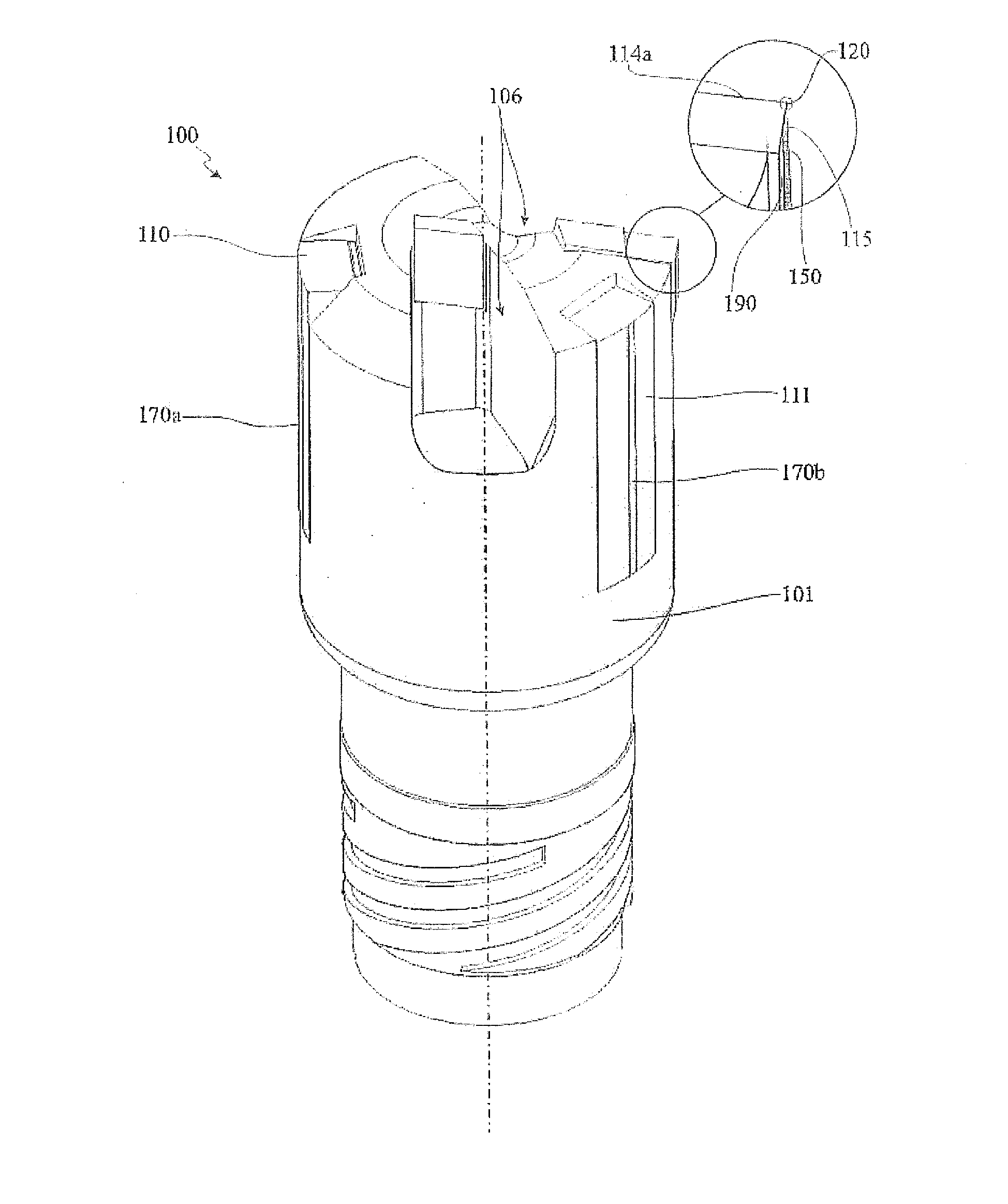
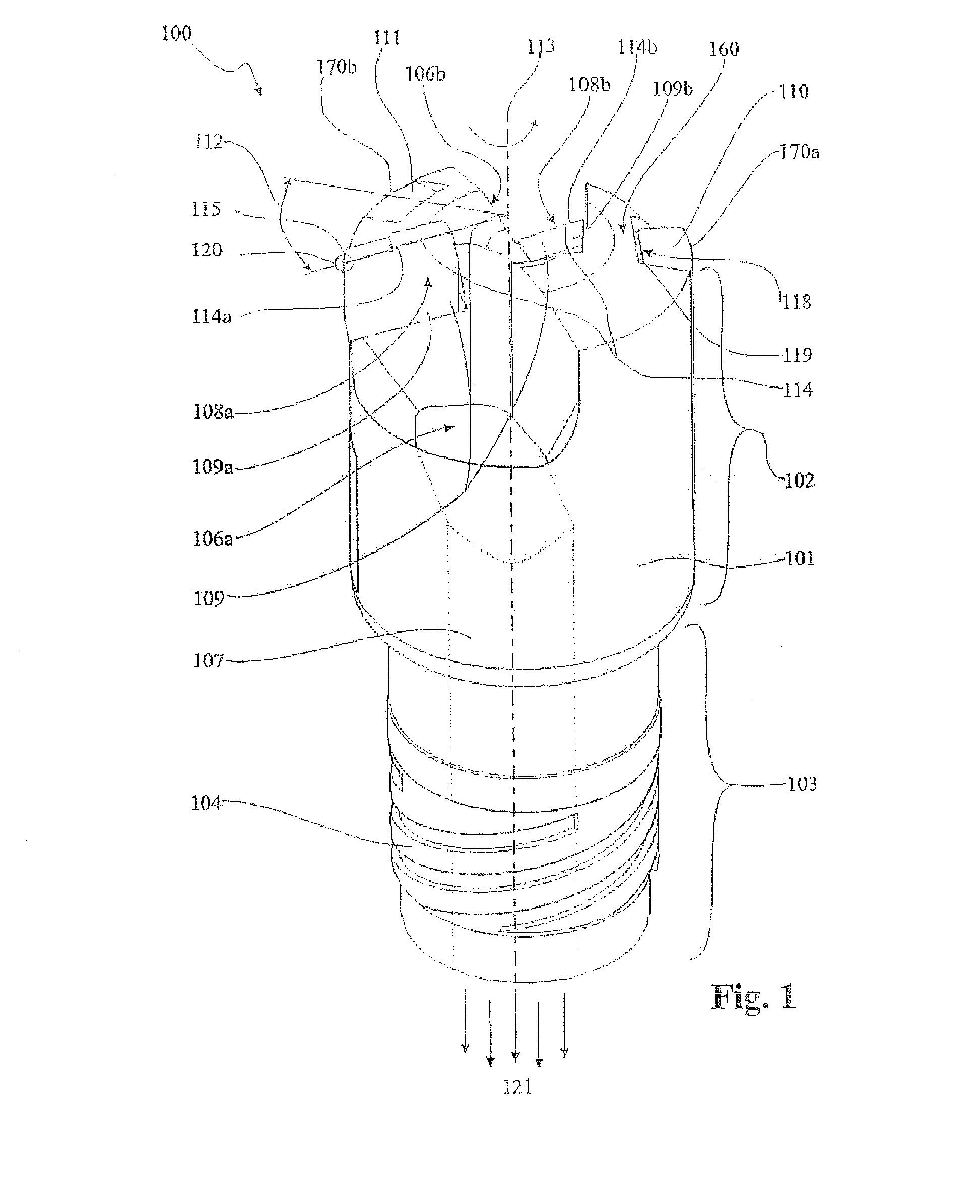
[0045]FIG. 1 illustrates in perspective illustration an exemplary embodiment of a drill head 100 with a cutting edge 109 divided into two partial cutting edges 109a and 109b. The drill head 100 shown has an essentially cylindrical drill head body 101 rotatable about an axis of rotation 113 and with a drilling region 102 and a shank region 103. The shank region 103 is designed to be connected to a drill tube, not illustrated here. For the exemplary embodiment shown, a special connecting thread 104 is provided for tying the drill head 100 to the drill tube. This may be a customary single-start or quadruple-start connecting thread for BTA drill heads. In the case of very small drilling diameters in the range of approximately 7 mm to 12 mm, the drill head may even be incorporated directly into the drill tube. With large deep hole drilling tools, the drill head may also be flanged on.

[0046]The cutting edge 109 with its two partial cutting edges 109a and 109b, which form respectively an o...


PUM

PropertyMeasurementUnit
angleaaaaaaaaaa
angleaaaaaaaaaa
angleaaaaaaaaaa

Abstract

A drill head for a deep hole drilling tool. A drill head body is rotatable about an axis of rotation and has a drilling side and a cavity duct with a chip collecting orifice. A cutting edge has a main and a secondary cutting edge cant, the secondary cutting edge cant arranged on a radial outside of the cutting edge. The main and the secondary cutting edge cants form a cutting edge corner and span a rake which is arranged contiguously to the chip collecting orifice. A first guide pad is arranged in a circumferential half, facing away from the rake, and a second guide pad is arranged diametrically opposite the cutting edge corner. The first guide pad can be offset to the cutting edge corner by the amount of a guide pad angle in the circumferential direction of the drill head The guide pad angle amounts to less than 70°.

Description

BACKGROUND OF THE INVENTION[0001]The invention relates to a drill head for a deep hole drilling tool for BTA / STS or ejector deep hole drilling according to the precharacterizing clause of claim 1 and to a deep hole drilling tool according to the precharacterizing clause of claim 12.[0002]Deep hole drilling is a special drilling method which is employed above all for making boreholes with a diameter of 1 mm to 1500 mm to a depth of more than three times the diameter, while even very deep boreholes with a depth / diameter ratio greater than 200 can be made. A deep hole drilling tool is usually composed of a drill shank which is also designated in the case of deep hole drilling tools as a drill tube and acts as an extension piece and of a drill head which is attached to the front end of the drill shank and on which one or more cutting edges are arranged.[0003]What is characteristic of deep hole drilling is a continuous supply of cooling lubricant under pressure and continuous chip discha...

Claims


Application Information

Patent Timeline
Patent Type & Authority Applications(United States)
IPC IPC(8): B23B51/06B23B51/00
CPCB23B51/0493B23B2251/422B23B2251/56Y10T408/45B23B51/0054B23B51/06B23B2260/004B23B51/063B23B51/04B23B51/02
Inventor RANDECKER, HERMANNBERNT, ANDREAS
Owner TBT TIEFBOHRTECHN
Why Eureka
Try Eureka