Method for determining a position change of a tool and the tool and the tool control unit

a technology of tool control unit and position change, which is applied in the direction of instruments, auxiliary welding devices, soldering apparatuses, etc., can solve the problem that the device has no gripping element for a worker in particular

Inactive Publication Date: 2013-04-04
DRITTE PATENTPORTFOLIO BET GMBH & CO KG
View PDF13 Cites 98 Cited by
  • Summary
  • Abstract
  • Description
  • Claims
  • Application Information

AI Technical Summary

Benefits of technology

[0018]Another core aspect of the present invention is that the method according to the invention is independent of the tool geometry or a sensor which may be fitted to the tool. Instead, the method according to the invention is an indirect measurement method which also allows a high degree of flexibility with respect to the positioning of such sensors on the tool. The tool geometry in this instance may be used in order to support the method, but this is not necessary since initially the tool position is aligned with a reference position in order to determine at least a first position vector. The independence of the method according to the invention from the geometric conditions of the tool or from a potential positioning of the sensor on the tool further allows the method to be carried out by way of a retrofittable orientation determination unit on a tool having a tool control unit which is already provided.
[0040]According to a particularly preferred embodiment of the tool according to the invention or the tool control unit, the data which are produced by way of at least one sensor which is fitted to the tool are transmitted by way of a fixed conductor to the tool control unit or to a detection unit which co-operates with the tool control unit. Alternatively, the transmission may also be carried out in a wireless manner. Whilst the wireless transmission can be carried out, for example, by way of radio waves, the fixed conductor for transmitting the data produced by the sensor may be included together with other lines in a hose assembly which connects the tool and tool control unit. Both embodiments allow substantially unimpeded handling of the tool during the working operation. In particular, the use of a wireless sensor which itself co-operates with a detection unit which co-operates with the tool control unit allows an advantageous retrofitting of the tool and tool control unit so that they can also exploit the advantages and flexibility of the orientation or position determination.

Problems solved by technology

Such automatic devices particularly have no gripping element for a worker.

Method used


Image

  • Method for determining a position change of a tool and the tool and the tool control unit
  • Method for determining a position change of a tool and the tool and the tool control unit
  • Method for determining a position change of a tool and the tool and the tool control unit

Examples


Embodiment Construction

[0055]In the following description, the same reference numerals are used for components which are the same or which have the same effect.

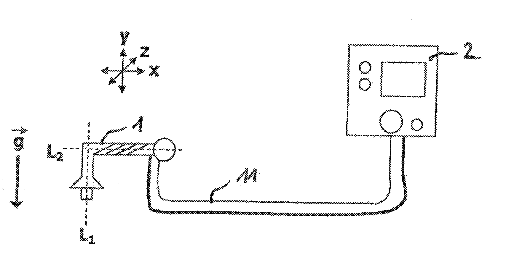
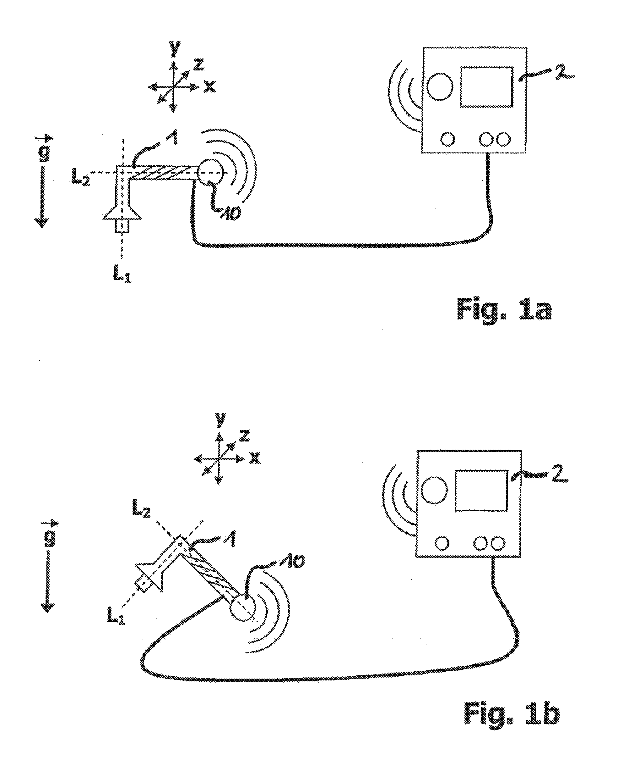
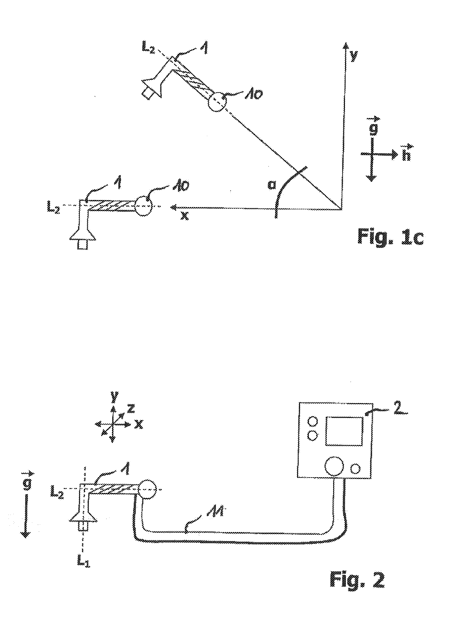
[0056]FIG. 1a is a schematic side view of a first embodiment of the tool 1 according to the invention having a tool control unit 2. In this instance, the tool 1 is preferably a welding tool. However, every other advantageous tool form according to the construction is also included by the illustration of the tool 1. The tool 1 is first freely arranged in space, which is illustrated by the schematically indicated coordinate system having the axes x, y and z. The tool 1 is preferably arranged with a fixedly predetermined arrangement relative to the direction of the field of gravitational acceleration, which is illustrated in this instance by {right arrow over (g)}. In this instance, the arrangement can be determined either relative to the axis L2 which is orientated in the longitudinal extent direction of the handle of the tool 1, or along the axis L1...


PUM


Abstract

A method for determining a position change of a handheld tool in space includes: alignment of an initial tool position with a reference position to determine at least a first position vector of the tool, at least one component of the first position vector being determined by measurement of a component of the gravitational acceleration in the direction of a predetermined axis of the tool;establishing a modification of the tool position during an actual position change by determining at least one angular discrepancy of a second position vector of at least one temporally preceding position vector, at least one component of the second position vector being determined after the position change by measuring the component of the gravitational acceleration in the direction of the predetermined axis of the tool; and providing information relating to the orientation of the tool established from the at least one angular discrepancy.

Description

BACKGROUND OF THE INVENTION[0001]The invention relates to a method for determining a position change of a handheld tool in space and a tool and tool control unit for carrying out such a method.[0002]In spite of significantly advancing technological development, for instance, in the field of robot technology, handheld tools continue to be highly sought after, in particular for specific applications and for applications which are not advantageous on an industrial scale. In this instance, a material is processed by way of a handheld tool which is manually handled by an operator or a worker. However, in order to achieve satisfactory operating results, a high level of skill and long-term experience in handling the tool are sometimes required. Depending on the requirements or the task, the worker adapts the operating properties of the tool. Typically, modifications of the control parameters in the tool control unit are carried out for this purpose, whereby the tool can be used in various ...

Claims


Application Information

Patent Timeline
Patent Type & Authority Applications(United States)
IPC IPC(8): G01B21/16
CPCG01B21/16B23K37/0258B23K37/0205B25F5/00B23Q15/013B23Q15/22B23Q17/22
Inventor DELIN, MARCUSFUCHS, NORMEN
Owner DRITTE PATENTPORTFOLIO BET GMBH & CO KG
Why Eureka
Try Eureka