
Optical lens, light-emitting diode optical component and light-emitting diode illumination lamp

a technology of optical components and optical lenses, applied in the direction of point-like light sources, lighting and heating apparatuses, lighting device details, etc., can solve the problem of not being able to provide direct uniform luminance, and achieve uniform luminance distribution and uniform illumination distribution

Inactive Publication Date: 2013-04-04
NAT APPLIED RES LAB
View PDF7 Cites 20 Cited by
  • Summary
  • Abstract
  • Description
  • Claims
  • Application Information

AI Technical Summary

Benefits of technology

The present invention provides an optical lens that can make a high-directional LED emit light in a way that results in a uniform illumination. This lens is different from other similar lenses and can help to create an even and bright illuminated area.

Problems solved by technology

In general, the small-sized and high-directional radiant LEDs cannot directly provide uniform luminance to an environment such as indoor illumination or outdoor illumination, i.e., the LEDs can provide uniform luminance and change light path thereof by incorporating with optical components (e.g., reflection mirror or lens) of secondary optics design.

Method used


Image

  • Optical lens, light-emitting diode optical component and light-emitting diode illumination lamp
  • Optical lens, light-emitting diode optical component and light-emitting diode illumination lamp
  • Optical lens, light-emitting diode optical component and light-emitting diode illumination lamp

Examples


Embodiment Construction

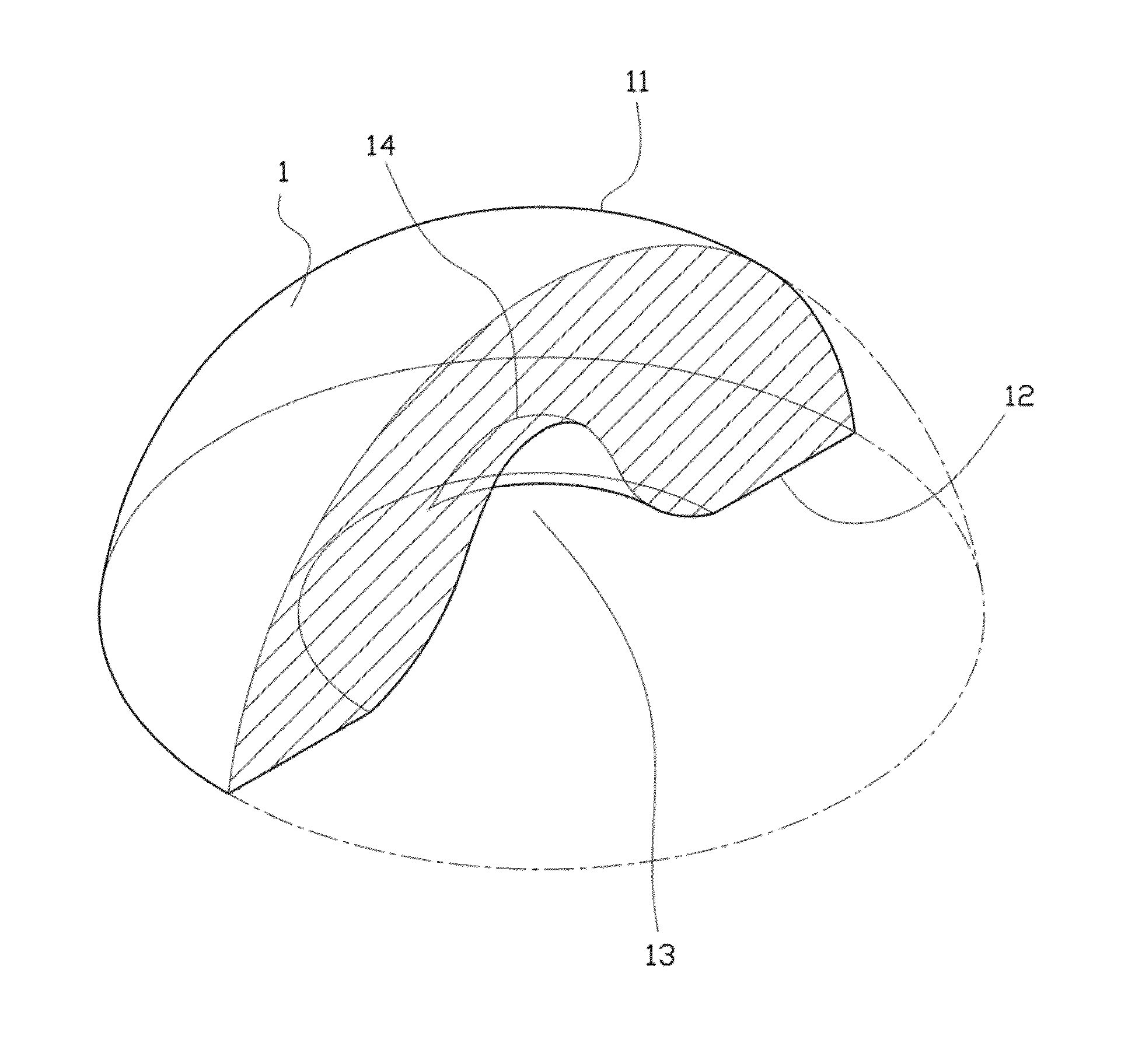
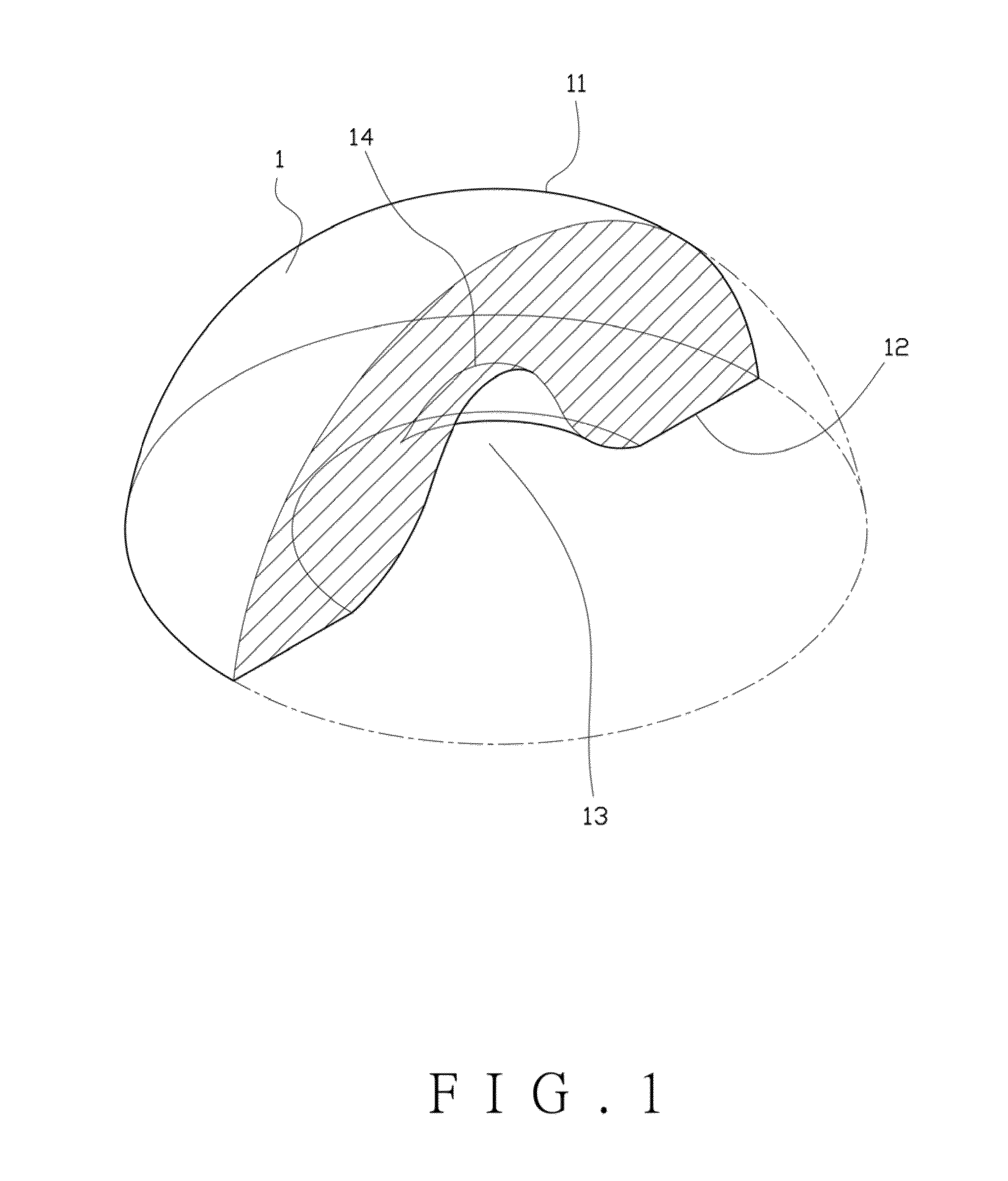
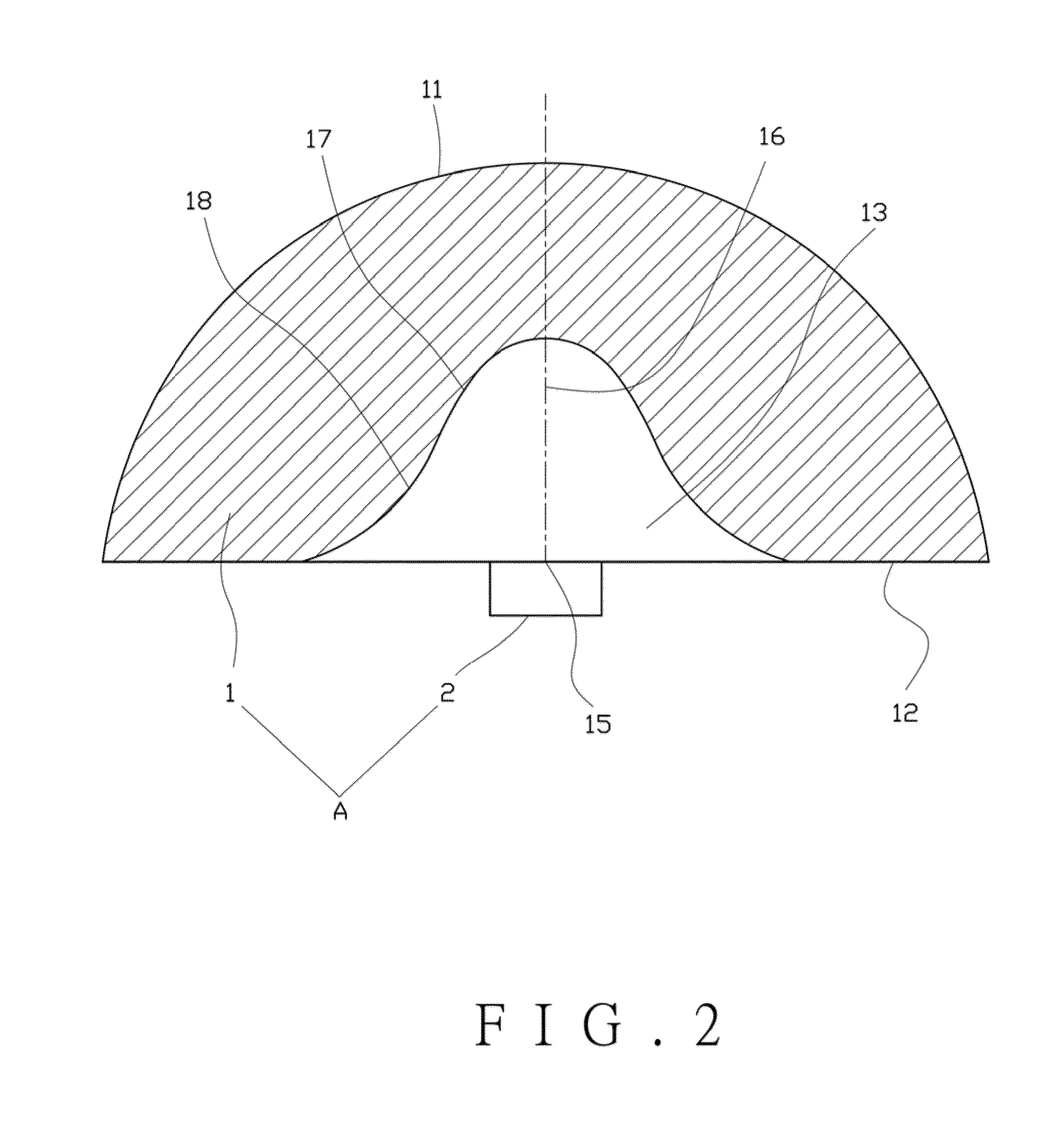
[0030]The following description is of the best-contemplated mode of carrying out the invention. This description is made for the purpose of illustrating the general principles of an optical lens, a light-emitting diode (LED) optical component and a light-emitting diode (LED) illumination lamp of the invention and should not be taken in a limiting sense. The scope of the invention is best determined by reference to the appended claims.

[0031]Referring to FIGS. 1 and 2, a LED component ‘A’ comprises an optical lens 1 and a LED 2 bonded to the optical lens 1. The optical lens 1 formed as a semi-spherical shape comprises an uplifting spherical surface 11 and a bottom surface 12 corresponding to the spherical surface 11, wherein the bottom surface12 includes an inward space 13 concave to the spherical surface 11 and formed with a free surface 14 corresponding to the spherical surface 11, a center of the bottom surface 12 is included with a focus 15, and the free surface 14 is axially-symm...


PUM


Abstract

The invention is related to an optical lens, a light-emitting diode optical component and a light-emitting diode illumination lamp. The optical lens formed as a semi-spherical shape includes an uplifting spherical surface and a bottom surface corresponding to the spherical surface, and the bottom surface includes an inward space concave to the spherical surface and formed with a free surface corresponding to the spherical surface. The free surface is axially-symmetrical formed as rotational molding with respect to an axis connected from the focus to a center point of the spherical surface, to form the free surface with a similar Gaussian distribution curve provided on a section vertically cut from the spherical surface to the bottom surface. A light-emitting diode is disposed below the focus of the optical lens. The special outline structure of the optical lens can provide a uniform luminance distribution on an illuminating area.

Description

BACKGROUND OF THE INVENTION[0001]1. Field of the Invention[0002]The present invention relates to an optical lens, a light-emitting diode optical component and a light-emitting diode illumination lamp, and in particular relates to an optical lens capable of enabling a high-directional radiant light-emitting diode to emit a uniform scattering light and providing an illuminating area with a uniform luminance distribution, and a light-emitting diode optical component and a light-emitting diode illumination lamp which are equipped with the optical lens.[0003]2. Description of the Related Art[0004]With the increasing of luminous power and heat-dissipation efficiency and the advantages of environmental protection and low power consumption of light-emitting diodes (LEDs), traditional light sources such as fluorescent lamps and incandescent lamps have been gradually replaced by the LEDs. In general, the small-sized and high-directional radiant LEDs cannot directly provide uniform luminance t...

Claims


Application Information

Patent Timeline
Patent Type & Authority Applications(United States)
IPC IPC(8): F21V5/04
CPCF21V5/007F21V5/04F21Y2101/02F21V5/046F21Y2115/10
Inventor FANG, YU-BINLIN, CHI-FENGYANG, PO-HUA
Owner NAT APPLIED RES LAB
Learn More