Random packing elements and column containing same

a technology of random packing elements and columns, applied in transportation and packaging, separation processes, chemical/physical/physicochemical processes, etc., can solve the problems of reducing the efficiency of mass transfer, and reducing the effective surface area of mass and/or heat transfer of elements, etc., to achieve uniform surface area distribution, improve mass transfer efficiency, and less restricted fluid flow paths

Active Publication Date: 2008-04-10
KOCH GLITSCH INC
View PDF4 Cites 10 Cited by
  • Summary
  • Abstract
  • Description
  • Claims
  • Application Information

AI Technical Summary

Benefits of technology

[0010]In accordance with one embodiment of the present invention, at least about 20 percent of the total surface area of the random packing element is defined within the interior volume. Compared to random packing elements of the prior art, the shape and configuration of the inventive element increase mass transfer efficiency by providing a more uniform surface area distribution and less restricted fluid flow paths when the packing elements are positioned in multiple different rotational orientations within a packed bed in a reactor or column.

Problems solved by technology

One disadvantage of the random packing elements of the prior art is that often the performance of the element is highly dependent on its configuration and its orientation with respect to the direction of flow of fluid streams through the element within the packed bed.
In addition, the large surface area in the direction perpendicular to the longitudinal axis of the Pall ring is disadvantageous in that it tends to “shield” or inhibit fluid flow through immediately adjacent rings in the downstream flow direction.
While the packing element disclosed in the '536 patent provides improvements over other random packing elements of the prior art, it also includes limitations that can hinder its performance.
This shielding effect can reduce mass transfer efficiency by reducing the element's effective surface area for mass and / or heat transfer.

Method used


Image

  • Random packing elements and column containing same
  • Random packing elements and column containing same
  • Random packing elements and column containing same

Examples


example 1

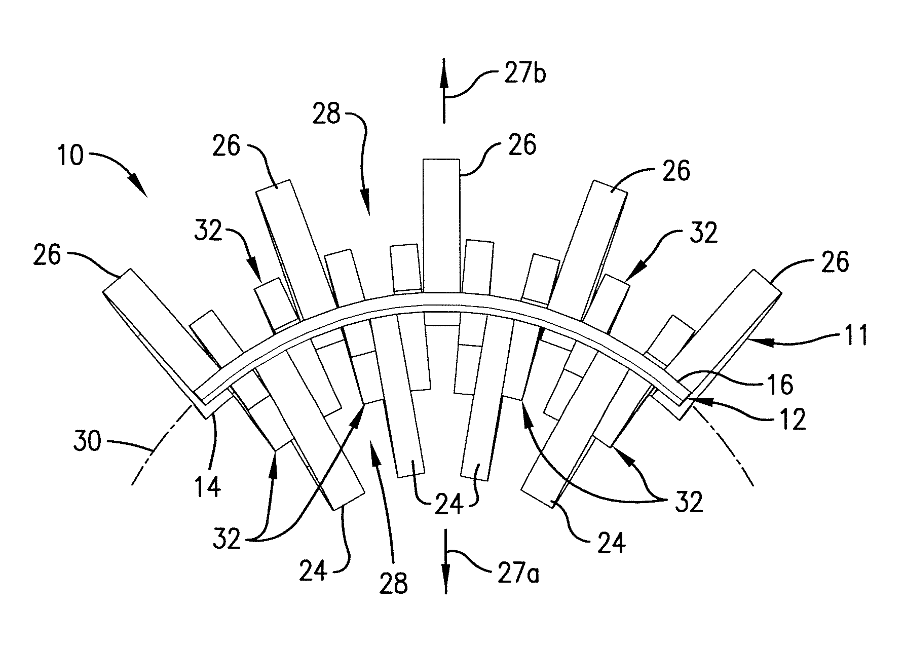
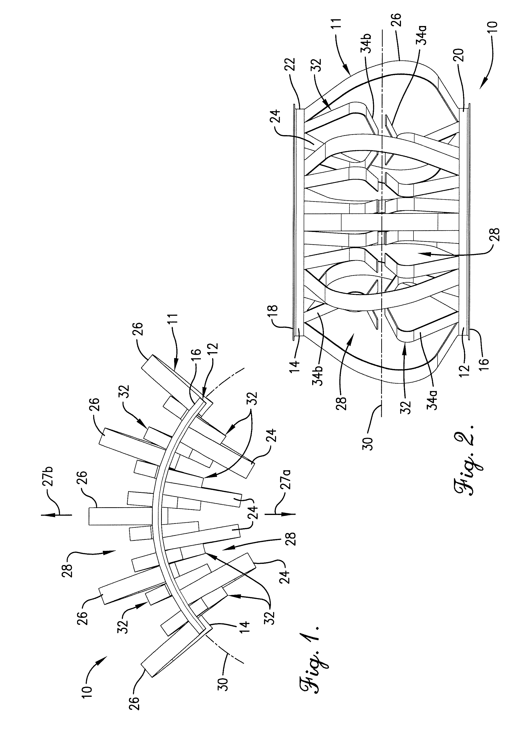
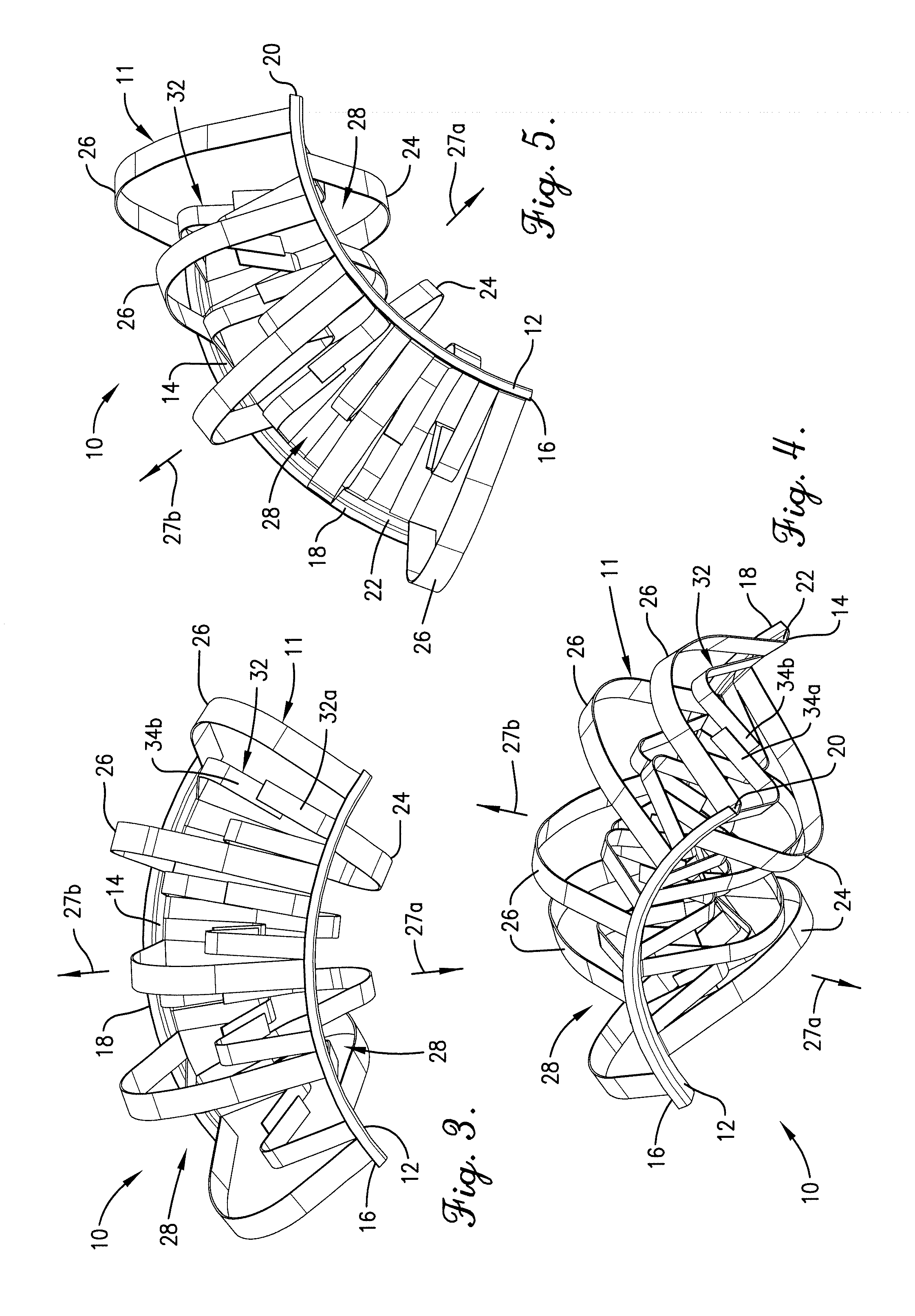
[0039]The mass transfer coefficient was calculated for three different random packing elements: Comparative Element 1, a saddle-shaped random packing of the type illustrated in U.S. Pat. No. 4,303,599; Comparative Element 2, a saddle-shaped random packing element of the type illustrated in U.S. Pat. No. 5,882,772; and Inventive Element 3, the packing element 10 illustrated in FIGS. 1-13.

[0040]The mass transfer coefficient for each packing element was calculated for each of ten different packing orientations, labeled A through I in Table 1, below. Orientations A through I correspond to the element being positioned at 0°, 45°, and 90° from the base position for each of the three Cartesian axes. For each packing element, the mass transfer coefficient range was determined by subtracting the minimum from the maximum mass transfer coefficient among each position A through I. The average mass transfer coefficient for each packing element was then determined by averaging the individual mass...

example 2

[0043]Testing was conducted comparing the performance of the Inventive Element (packing element 110 shown in FIGS. 14-26) to that of four types of commercially-available random packings. A mixture of light hydrocarbons was distilled at total reflux. The tower was run at a pressure significantly higher than atmospheric pressure—very typical of the conditions at which these mixtures are being processed in industry, and very typical for the conditions at which random packing is often used. The tower diameter and bed depth were large enough to ensure that industrially relevant data were generated. Liquid samples from above and below the packed bed were analyzed to measure the packing efficiency. The maximum capacity of the packing was determined by increasing the heat input until the pressure drop increased very steeply with any additional heat input and entrainment from the top of the bed was significant (loss of efficiency). The results of the comparative testing are presented in Tabl...


PUM

PropertyMeasurementUnit
widthaaaaaaaaaa
widthaaaaaaaaaa
widthaaaaaaaaaa

Abstract

A saddle-shaped random packing element is provided with laterally spaced, arcuate side members and a plurality of inner and outer rib elements that extend from and between the side members to form an interior volume. At least one lesser rib element extends from the side members and is at least partially positioned within the interior volume so that at least about 20 percent of the surface area of the packing element is positioned within the interior volume.

Description

CROSS-REFERENCE TO RELATED APPLICATION[0001]This application claims the priority benefits under 35 U.S.C. § 119(e) of provisional application Ser. No. 60 / 828,900, filed on Oct. 10, 2006, the entirety of the disclosure of which is hereby specifically incorporated herein by this reference thereto.BACKGROUND OF THE INVENTION[0002]The present invention relates generally to mass transfer devices for use with chemical process and mass transfer reactors and columns and, more particularly, to random packing elements for use in such reactors and columns. The invention also relates to methods of making and using such random packing elements.[0003]Random or dumped packing elements are normally employed in gas-liquid or liquid-liquid contact towers or columns to provide mass transfer surfaces between a downwardly flowing fluid, typically a liquid stream, and an upwardly ascending fluid, typically gas or vapor stream or another liquid stream. Random packing elements may be used in a variety of c...

Claims


Application Information

Patent Timeline
Patent Type & Authority Applications(United States)
IPC IPC(8): B01J19/30
CPCB01J19/30B01J2219/30203B01J2219/30211B01J2219/30261Y10T428/24628B01J2219/30408B01J2219/30466Y10S261/72B01J2219/30296B01D3/26B01D15/08B01D53/18
Inventor NIEUWOUDT, IZAK
Owner KOCH GLITSCH INC
Why Eureka
Try Eureka