Formation of large arrays of zinc oxide nanostructures using electrodeposition

a technology arrays, which is applied in the field of large arrays of zinc oxide nanostructures formed using electrodeposition, can solve the problems of unproven mass-production feds for the consumer market, and achieve the effects of enhancing the utility of nanostructures, efficient electron emitters, and uniform cross-sectional area

a technology arrays, which is applied in the field of large arrays of zinc oxide nanostructures formed using electrodeposition, can solve the problems of unproven mass-production feds for the consumer market, and achieve the effects of enhancing the utility of nanostructures, efficient electron emitters, and uniform cross-sectional area

US20090011224A1Inactive Publication Date: 2009-01-08NOVAKOR

Image

  • Formation of large arrays of zinc oxide nanostructures using electrodeposition
  • Formation of large arrays of zinc oxide nanostructures using electrodeposition
  • Formation of large arrays of zinc oxide nanostructures using electrodeposition

Examples


Embodiment Construction

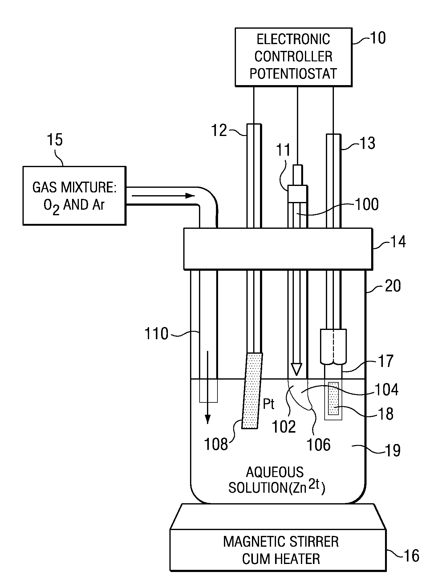
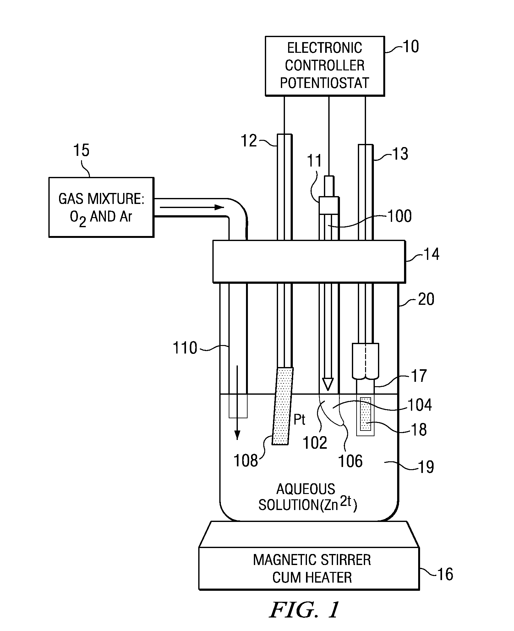
[0017]FIG. 1 depicts laboratory bench apparatus for carrying out the process of the invention. In a vessel 20 is placed an aqueous solution 19 of a water-soluble zinc salt. It is preferred that the zinc salt be selected from zinc nitrate, zinc chloride and mixtures thereof. It is particularly preferred to use ZnCl2. The zinc salt should be present in a concentration in the range of about 0.0001 M to 0.03 M. Preferably the zinc salt should be present in a concentration from 0.0007 M to 0.009 M. Most preferably the zinc salt should be present in a concentration from 0.001 M to 0.007 M.

[0018]The solvent preferably is deionized water in order to eliminate impurities in crystal formation. It is preferred that the solution also contain a supporting electrolyte such as KCl, EuCl2 or KNO3. Preferably the supporting electrolyte should be present in concentrations of 0.001 M to 0.3 M. More preferably the supporting electrolyte should be present in concentrations of 0.009 M to 0.03 M. It is pr...


PUM

PropertyMeasurementUnit
Temperatureaaaaaaaaaa
Lengthaaaaaaaaaa
Timeaaaaaaaaaa

Abstract

In an aqueous solution of a zinc salt, counter, reference and working electrodes are placed, and an electric potential is applied across the working and reference electrodes. A gas including oxygen and an inert gas is introduced into the aqueous solution. Responsive to these conditions an array of zinc oxide nanostructures grows on a conductive nucleation plate that is a part of the working electrode. The nanostructures have sharp tips, have a more efficient electron emissivity than nanorods made from other materials, and can be used in fabricating field emission lamps and displays.

Description

BACKGROUND OF THE INVENTION[0001]Much present-day scientific research involving information technology, display devices and the materials to make such devices is focused on nanotechnology in order to further advance miniaturization. One approach is from the bottom up, and concerns the synthesis of nanostructures which have utility in the semiconductor art. Zero-dimensional quantum dots, one-dimensional quantum wires, nanowires and nanorods have been widely suggested.[0002]International research efforts to synthesize nanostructures have included semiconductors such as silicon, germanium, Al—Ga—In—P—N systems, ZnO, SnO2 and SiC. In particular, the oxide semiconductor ZnO has a wurtzite structure with direct band-gap energy of 3.37 eV and a very high excition binding energy of 60 meV at room temperature. If problems concerning production can be overcome, ZnO based materials could replace conventional materials in areas which require high emission characteristics.[0003]Field emission di...

Claims


Application Information

Patent Timeline
08 Jan 2009
Publication
US20090011224A1
IPC
B32B5/16; C25D9/04; C25D5/10; C25D5/12
CPC
C25D1/02; C25D5/54; Y10T428/256; C25D1/006; C25D9/04; C25D5/56; G02F1/13; B82Y40/00
Inventors
NAGARAJAN, GANAPATHI SUBRAMANIAM; LEE, JUWON