
Nano-structured trampoline fiber gas sensor

a fiber optic and sensor technology, applied in the field of fiber optic gas sensors, can solve the problems of difficult to determine, difficult to use gc or laser absorption instruments online for monitoring an industrial process, and difficult to analyze a gas mixture,

Active Publication Date: 2013-04-04
FIBERGUIDE LTD
View PDF3 Cites 13 Cited by
  • Summary
  • Abstract
  • Description
  • Claims
  • Application Information

AI Technical Summary

Benefits of technology

The patent describes a new type of gas sensor made using a special fiber structure. This fiber structure includes a core fiber with at least one Bragg grating (a type of fiber optic structure) that defines a specific region, a fiber cladding that contacts the core fiber along its entire length, and a sensing matrix structure that is placed on the outer surface of the fiber cladding. The sensing matrix structure is made up of a high-coefficient of thermal expansion material layer (which can expand and contract with changes in temperature) and a bonding layer that helps to attach the sensing layer to the fiber cladding. This new gas sensor design has the ability to detect changes in temperature caused by the presence of specific gases, making it highly effective for use in various applications.

Problems solved by technology

However, using GC or laser absorption instrument online for monitoring an industrial process, such as analyzing a gas mixture, including multiple gas compositions, is challenging due to time-consuming and complicated instrument field calibration.
Although, gas characteristics, such as gas molecular weight, are desired to be known, they are not easily determinable and a standard design with nominal value is used for compressor efficiency prediction and control.
The technical barrier for using FBG for measuring gas is due mainly to the chemical inactive nature of the silicon dioxide fiber material.
However, it is difficult to analyze a gas mixture that has multi-component, where the interference from different gases could greatly degrade the sensor's accuracy and reliability.
Another challenge is that the sensing layer could be contaminated by real industrial environment where the oil mists, particle deposits, and polymerization may exist.

Method used


Image

  • Nano-structured trampoline fiber gas sensor
  • Nano-structured trampoline fiber gas sensor
  • Nano-structured trampoline fiber gas sensor

Examples


Embodiment Construction

[0030]In the following specification and the claims, which follow, reference will be made to a number of terms, which shall be defined to have the following meanings.

[0031]The singular forms “a”, “an” and “the” include plural referents unless the context clearly dictates otherwise.

[0032]“Optional” or “optionally” means that the subsequently described event or circumstance may or may not occur, and that the description includes instances where the event occurs and instances where it does not.

[0033]It is also understood that terms such as “top,”“bottom,”“outward,”“inward,” and the like are words of convenience and are not to be construed as limiting terms. Furthermore, whenever a particular feature of the invention is said to comprise or consist of at least one of a number of elements of a group and combinations thereof, it is understood that the feature may comprise or consist of any of the elements of the group, either individually or in combination with any of the other elements of...


PUM

PropertyMeasurementUnit
thicknessaaaaaaaaaa
thicknessaaaaaaaaaa
thicknessaaaaaaaaaa

Abstract

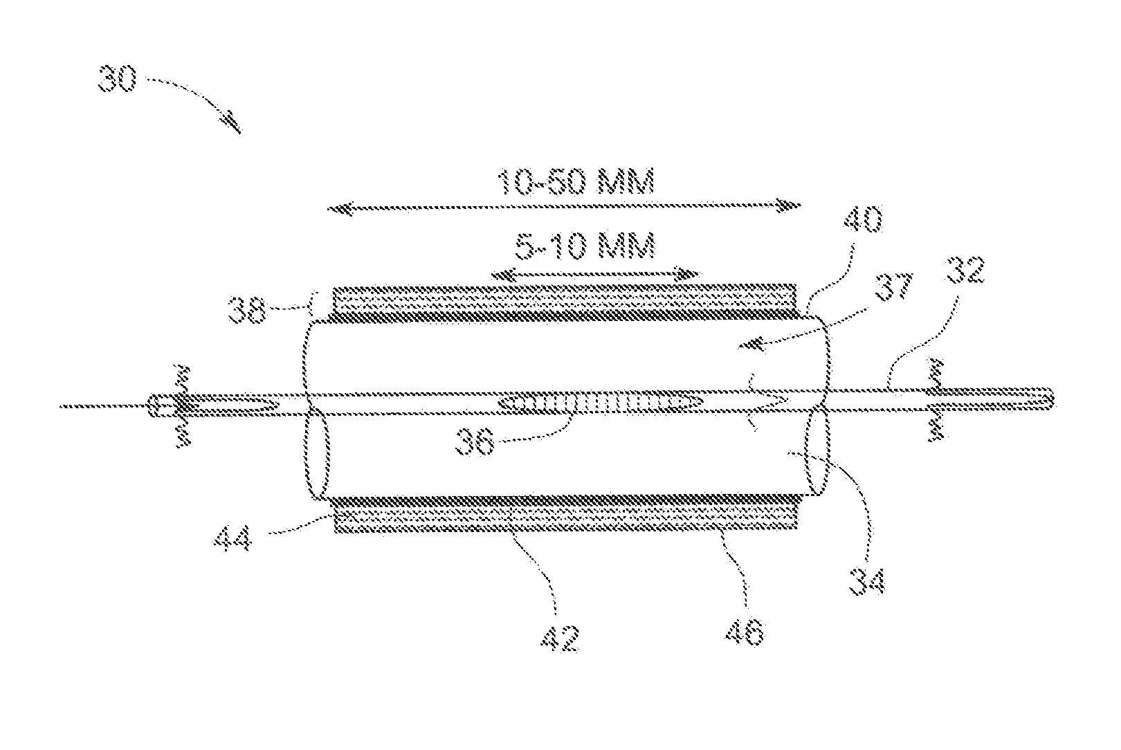
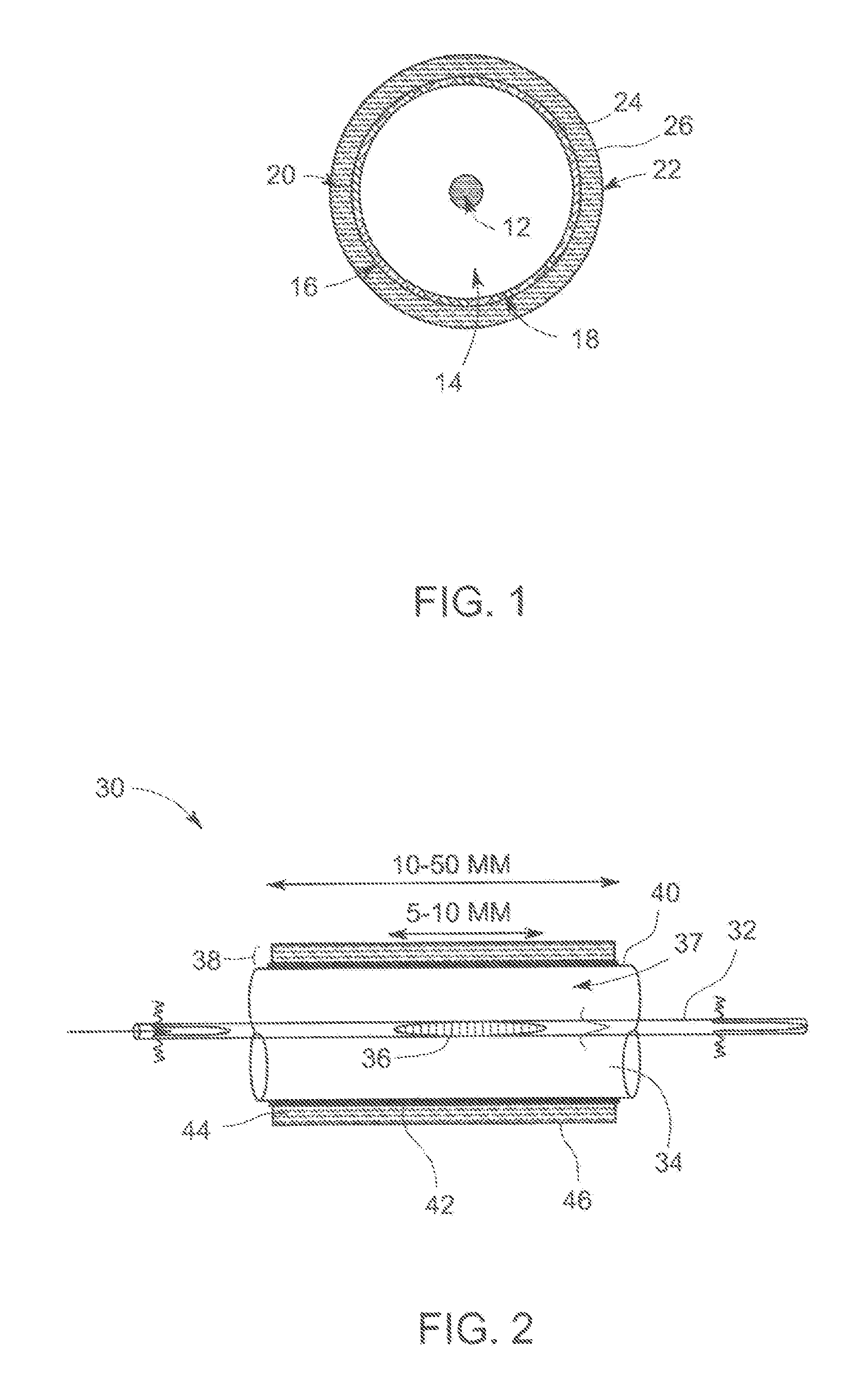
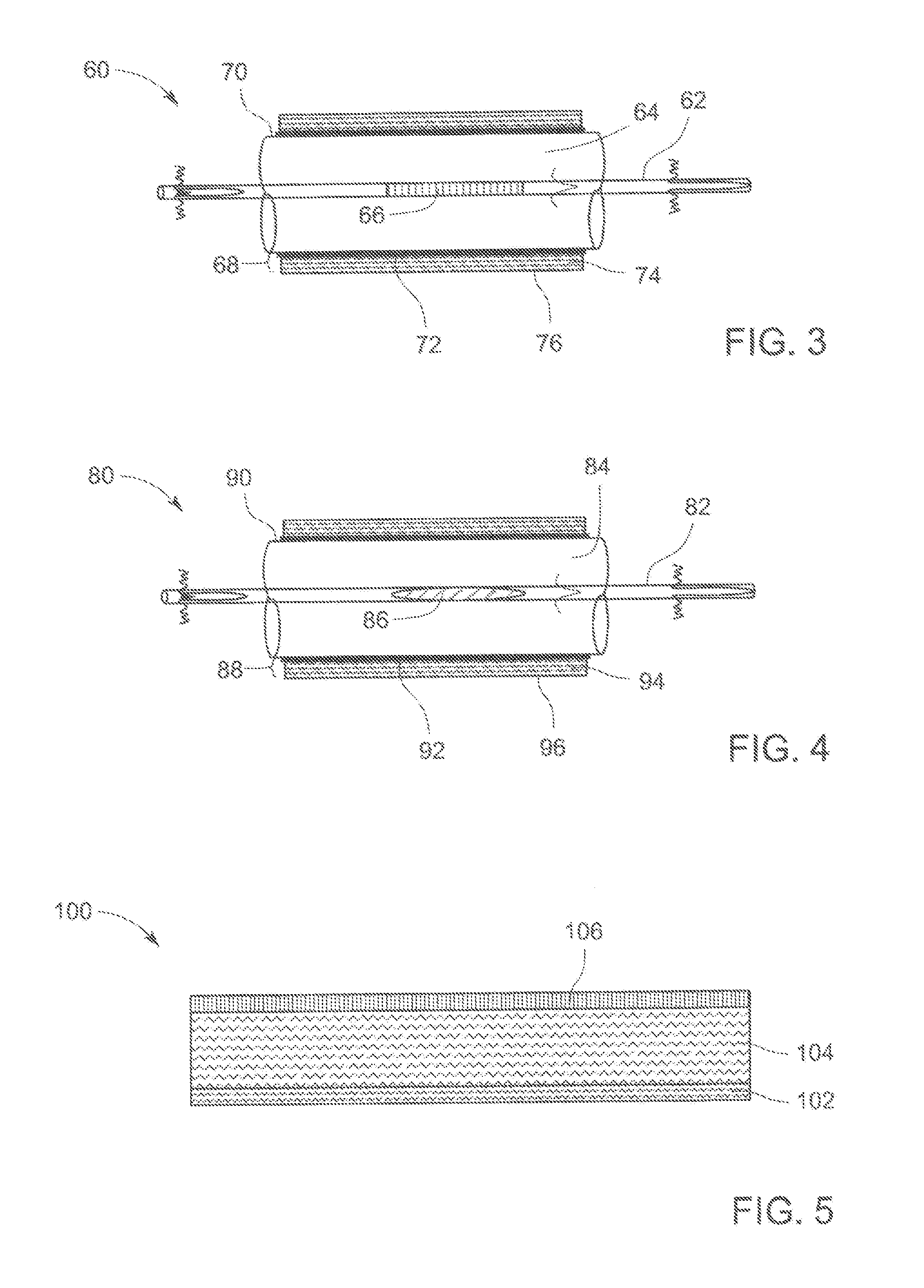
A fiber gas sensor including a core fiber comprising at least one Bragg grating region, a fiber cladding in contact with the core fiber along an entire length of the core fiber, and a sensing matrix structure disposed upon the outer surface of the fiber cladding along a portion of the length of the fiber cladding and surrounding the fiber Bragg grating region. The sensing matrix structure comprising a bonding layer disposed on the outer surface of the fiber cladding layer, a nano-structured trampoline matrix layer disposed on the outer surface of the bonding layer and a capping layer disposed on the outer surface of the matrix layer. The thermally modulated response amplitude of the fiber gas sensor is found to linearly depend upon the gas molecular weight, and can be directly used to determine heat specific capacity ratio of Cp / Cv.

Description

CROSS-REFERENCE TO RELATED APPLICATIONS[0001]This application is a non-provisional application that claims priority to provisional U.S. Patent Application Ser. No. 61 / 540,600 filed on Sep. 29, 2011; the disclosure of which is hereby incorporated by reference.BACKGROUND[0002]The invention relates generally to a fiber optic gas sensor, and more particularly to a nano-structured trampoline integrated fiber Bragg grating sensing device for gas molecular weight detection.[0003]Fiber optic sensors are widely used in the oil and gas industry for monitoring down-hole and turbomachinery parameters such as pressure, temperature, gas composition, hydrocarbon flow and seismic status. Monitoring of such machine operation parameters or / and operation conditions may provide real-time control and optimization for production output and enable condition-based maintenance for prolonging a machine's lifetime. In general, simultaneously measuring both temperature and pressure can be practically done with...

Claims


Application Information

Patent Timeline
Patent Type & Authority Applications(United States)
IPC IPC(8): G02B6/00B82Y20/00
CPCB82Y20/00G01N21/45G01D5/35316G02B6/02123G02B6/02076
Inventor XIA, HUA
Owner FIBERGUIDE LTD
Learn More