Hydraulic circuit for hybrid electric transmission

a hybrid electric transmission and hydraulic circuit technology, applied in fluid gearings, transportation and packaging, gearings, etc., can solve the problems of packaging problems and most systems are expensive, and achieve the effect of little increase in axial length

Active Publication Date: 2013-04-11
FORD GLOBAL TECH LLC
View PDF5 Cites 41 Cited by
  • Summary
  • Abstract
  • Description
  • Claims
  • Application Information

AI Technical Summary

Benefits of technology

[0008]The torque converter and the drive shell are removably mountable on the front of the transmission housing similar to a conventional torque converter. Rather than attaching the torque converter to the engine mounting plate, a drive shell is attached to the mounting plate. The torque converter is free to rotate relative to the drive shell within the drive shell cavity, resulting in

Problems solved by technology

A problem facing HEV designers is how to cool the disconnect clutch and the rotor and stator portions of the electric motor.
Various air and liquid based cooli

Method used


Image

  • Hydraulic circuit for hybrid electric transmission
  • Hydraulic circuit for hybrid electric transmission
  • Hydraulic circuit for hybrid electric transmission

Examples


Embodiment Construction

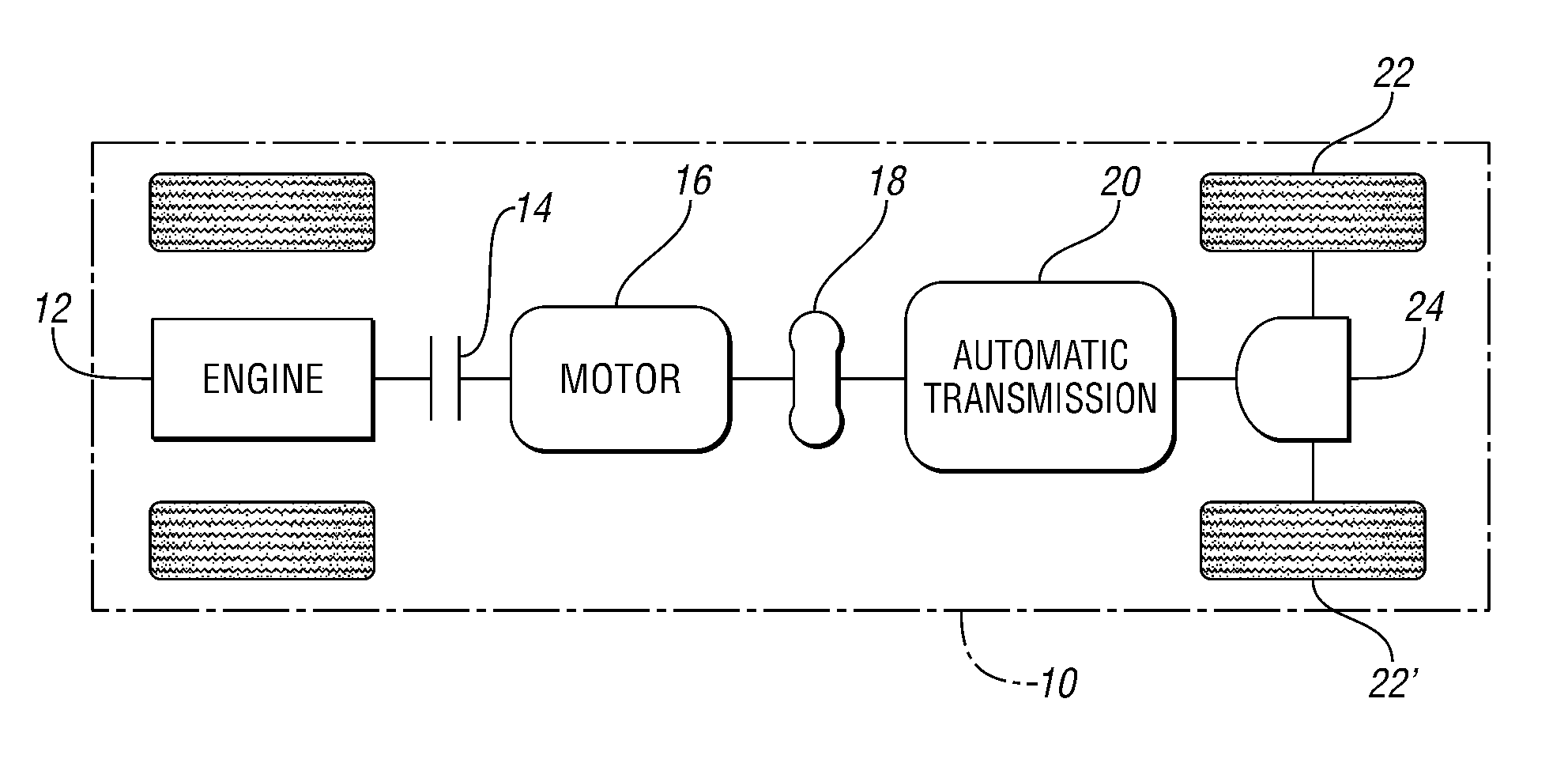
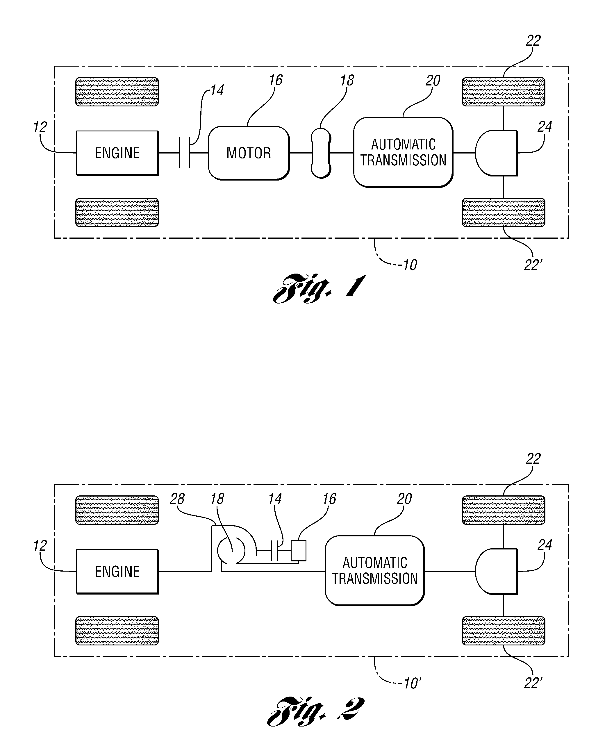
[0028]FIG. 1 illustrates a hybrid electric vehicle 10 schematically shown with a parallel type hybrid electric drive train. The hybrid electric vehicle is provided with an engine 12 having a rotary output which is connected to a disconnect clutch 14 which drives an electric motor 16. The output of the electric motor is connected to the input of torque converter 18, the output of which is connected to the input shaft of automatic transmission 20. In a conventional manner, the automatic transmission is connected to the driven wheels, 22, 22′ by a differential 24. In the schematic illustration, hybrid electric vehicle 10 is provided with a pair of non-driven wheels, however, alternatively, a transfer case and a second differential can be utilized in order to positively drive all of the vehicle's wheels. The engine, disconnect clutch, motor, torque converter and the automatic transmission are connected sequentially in series, as illustrated in FIG. 1.

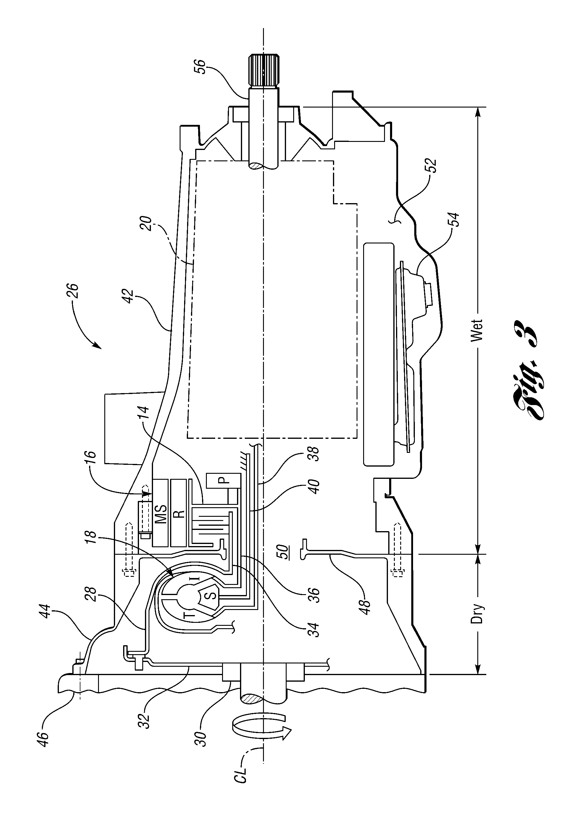
[0029]Motor / transmission assembly 26...


PUM


Abstract

A hydraulic circuit for a vehicle powertrain includes a first line for carrying fluid to a torque converter, a second line for carrying fluid from the torque converter, a third line for carrying fluid to a balance dam and an electric motor, and a fourth line for supplying actuating pressure to a clutch, said lines being coaxial.

Description

[0001]This application is a continuation-in-part of pending U.S. application Ser. No. 13 / 271,044, filed Oct. 11, 2011.TECHNICAL FIELD[0002]This invention relates to the powertrain of hybrid electric vehicles, particularly to a hydraulic circuit that supplies fluid to a torque converter, balance dam and motor and actuating pressure to a clutch.BACKGROUND[0003]Hybrid electric vehicles (HEVs) have both an internal combustion engine and an electric motor which can alternately or in combination be used to propel the vehicle. A variety of different drive trains are used in hybrid vehicles. The present application relates to a parallel configuration in which the engine is connected to the motor by a disconnect clutch with the motor driving the torque converter input of an automatic hydraulic transmission. The hydraulic transmission has an output which is connected to a differential coupled to the two driven wheels of the vehicle. This parallel hybrid electric vehicle drive chain power flow...

Claims


Application Information

Patent Timeline
IPC IPC(8): F15D1/00
CPCF16H45/00F16H2045/002B60K6/48Y02T10/6221Y10S903/912B60K6/387B60K6/40F16H61/62B60K6/26Y02T10/62Y10T137/8376
Inventor FRAIT, STEVEN A.THOMAS, STEVEN G.
Owner FORD GLOBAL TECH LLC
Why Eureka
Try Eureka