Flap support

a technology of support structure and flap, which is applied in the direction of aircraft transmission means, transportation and packaging, aircraft power plants, etc., can solve the problems of increasing maintenance cost and time, increasing manufacturing cost and assembly time, and prone to being relatively complex and heavy

Active Publication Date: 2013-04-11
AIRBUS OPERATIONS LTD
View PDF7 Cites 31 Cited by
  • Summary
  • Abstract
  • Description
  • Claims
  • Application Information

AI Technical Summary

Benefits of technology

[0021]The flap support beam may be mounted to the aircraft wing by a forward fitting and an aft fitting. Additional fittings may be provided as required. However, the provision of two fittings, fore and aft, has advantages for ease of assembly and removal of the flap support.

Problems solved by technology

However, it is common, particularly with more complex flap deployment geometry, to support the flap from the wing using a flap support structure.
Existing flap support structures tend to be relatively complex and heavy, leading to an increase in manufacturing cost and assembly time, increased maintenance cost and time, and in-service fuel costs due to the weight penalty.
They also tend to have a relatively large sectional area which impacts upon drag and hence in-service fuel costs.

Method used


Image

  • Flap support
  • Flap support
  • Flap support

Examples


Embodiment Construction

)

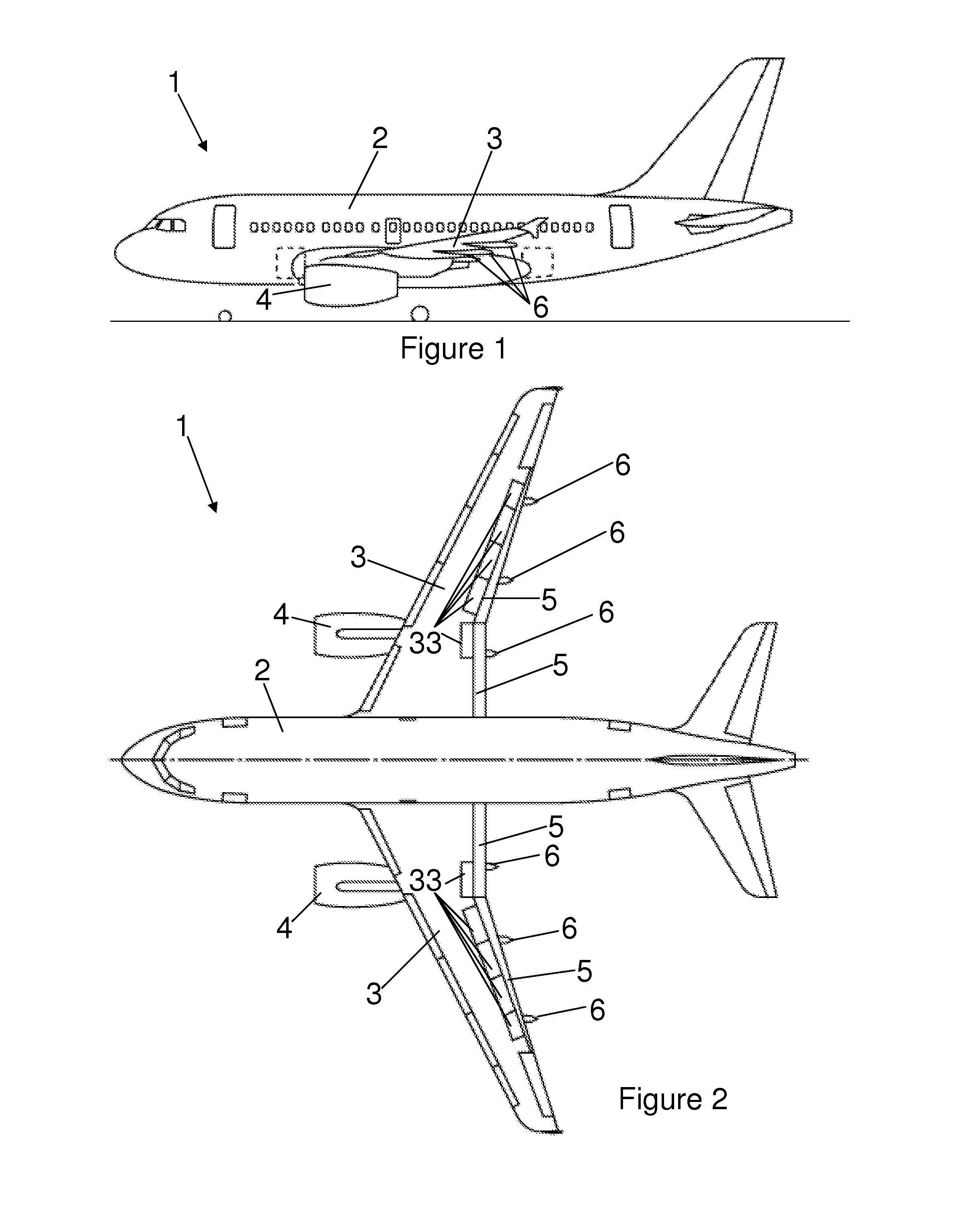
[0038]FIGS. 1 and 2 illustrate side and plan views, respectively, of an aircraft 1 having a fuselage 2, wings 3 and under-wing mounted engines 4. The wing 3 has moveable trailing edge flaps 5 mounted to the wing fixed trailing edge. The flaps 5 are supported by and moveable with respect to the fixed portion of the wing 3 by flap support structures 6. Whilst the aircraft shown in FIG. 1 is a commercial transport aircraft, the invention is applicable to a wide variety of aircraft types. It is also applicable to aircraft with engines mounted other than under the wing, e.g. aft mounted engines.

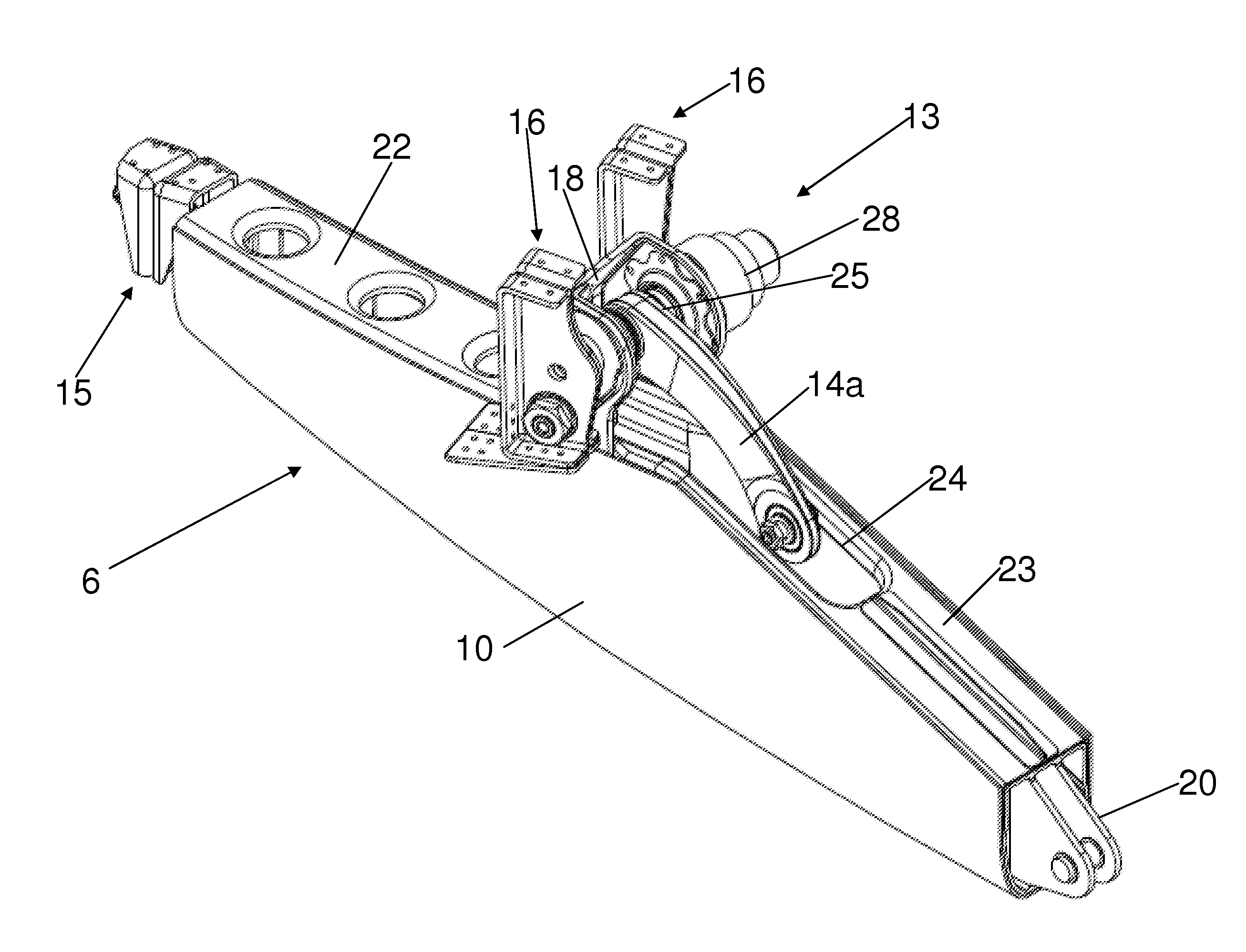
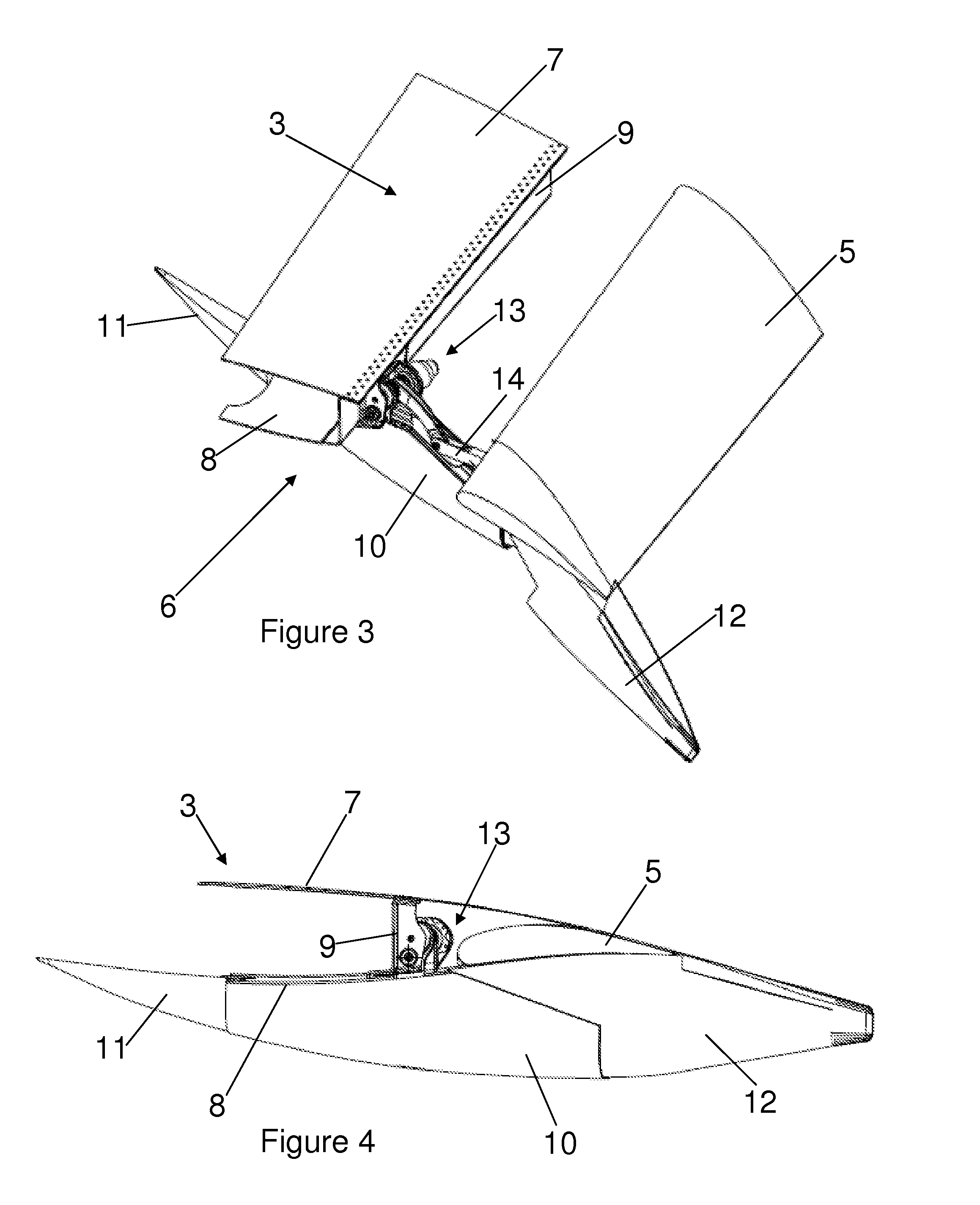
[0039]FIG. 3 illustrates a partially cut away view of the trailing edge of the wing 3 showing the flap support structure 6 with the flap 5 in an extended position. The wing 3 includes an upper wing cover 7, a lower wing cover 8 and a rear spar 9 which form part of a wing box structure for supporting the wing.

[0040]The flap support structure 6 generally includes a flap support beam 10, a fixed for...


PUM


Abstract

A flap support structure for an aircraft wing having a trailing edge flap, the flap support structure comprising: a flap support beam including an aerodynamic fairing; and a drive unit including a universal support structure which rotatably receives a drive shaft connected to a drive arm for moving the trailing edge flap, wherein the universal support structure also forms part of the flap support beam and supports the aerodynamic fairing.

Description

FIELD OF THE INVENTION[0001]The present invention relates to a flap support structure for an aircraft wing having a trailing edge flap.BACKGROUND OF THE INVENTION[0002]Aircraft typically include flaps attached to the wing fixed trailing edge which are movable between extended and retracted positions with respect to the fixed wing. Extension of the flaps increases the lift coefficient of the wing for the high lift, low speed flight phases (e.g. take-off and landing).[0003]There are a wide variety of flap designs (e.g. single and multiple flap elements, slotted, unslotted etc.) and flap actuation mechanisms (e.g. drop hinge, flap track etc.) to achieve a similarly wide variety of extended flap configurations and motion paths. Generally, the flap extension path includes at least some aft movement and / or downward rotation of the flap element(s). The aft movement increases the wing chord, whilst the downward rotation increases the wing camber.[0004]The flaps may be movable between a retr...

Claims


Application Information

Patent Timeline
Patent Type & Authority Applications(United States)
IPC IPC(8): B64C13/30B64C7/00B64C3/50
CPCB64C9/16Y02T50/32Y02T50/44B64C9/18Y02T50/30Y02T50/40B64C3/50B64C9/02
Inventor SOENARJO, MOCHAMAD-AGOES
Owner AIRBUS OPERATIONS LTD
Why Eureka
Try Eureka