Method and apparatus for magnetic resonance imaging

a magnetic resonance imaging and apparatus technology, applied in the field of methods and apparatuses for magnetic resonance imaging, can solve the problems of unwanted coherence paths, unwanted rephasing of signal contributions that should actually be suppressed, and unwanted signal contributions

Active Publication Date: 2013-04-11
SIEMENS HEALTHCARE GMBH
View PDF2 Cites 14 Cited by
  • Summary
  • Abstract
  • Description
  • Claims
  • Application Information

AI Technical Summary

Benefits of technology

[0012]An object of the invention is to provide an improved method and apparatus for magnetic resonance imaging. In particular, the invention has the object to provide a method and apparatus for magnetic resonance imaging wherein efficient gradient spoiling can be achieved with smaller gradient moments.

Problems solved by technology

Imaging sequences are known in which measures to suppress specific signal contributions are implemented in chronological sequence in different preparation modules, but such measures can lead to unwanted coherence paths.
The interaction of the spoiler gradient fields or spoiler RF fields that are used in different preparation modules can lead to an unwanted rephasing of the signal contributions that should actually be suppressed.
Unwanted signal contributions can also occur due to non-ideal conditions in the contrast preparation.
However, RF spoiling can be difficult to apply in certain methods or can deliver an insufficient suppression of unwanted coherence paths in which only a few preparation modules are used.
A conventional gradient spoiling in which the same gradient moment of the spoiler gradient field is always used in different preparation modules can lead, however, to unwanted coherence paths as described above.
Although such semi-empirical methods suppress unwanted signal coherences, they can lead to a rapid growth of the necessary gradient moments.
Given a large number of preparation modules, it is possible that the required large gradient moments can no longer be generated, or they may entail severe limitations in the temporal progression of the measurement sequence.

Method used


Image

  • Method and apparatus for magnetic resonance imaging
  • Method and apparatus for magnetic resonance imaging
  • Method and apparatus for magnetic resonance imaging

Examples


Embodiment Construction

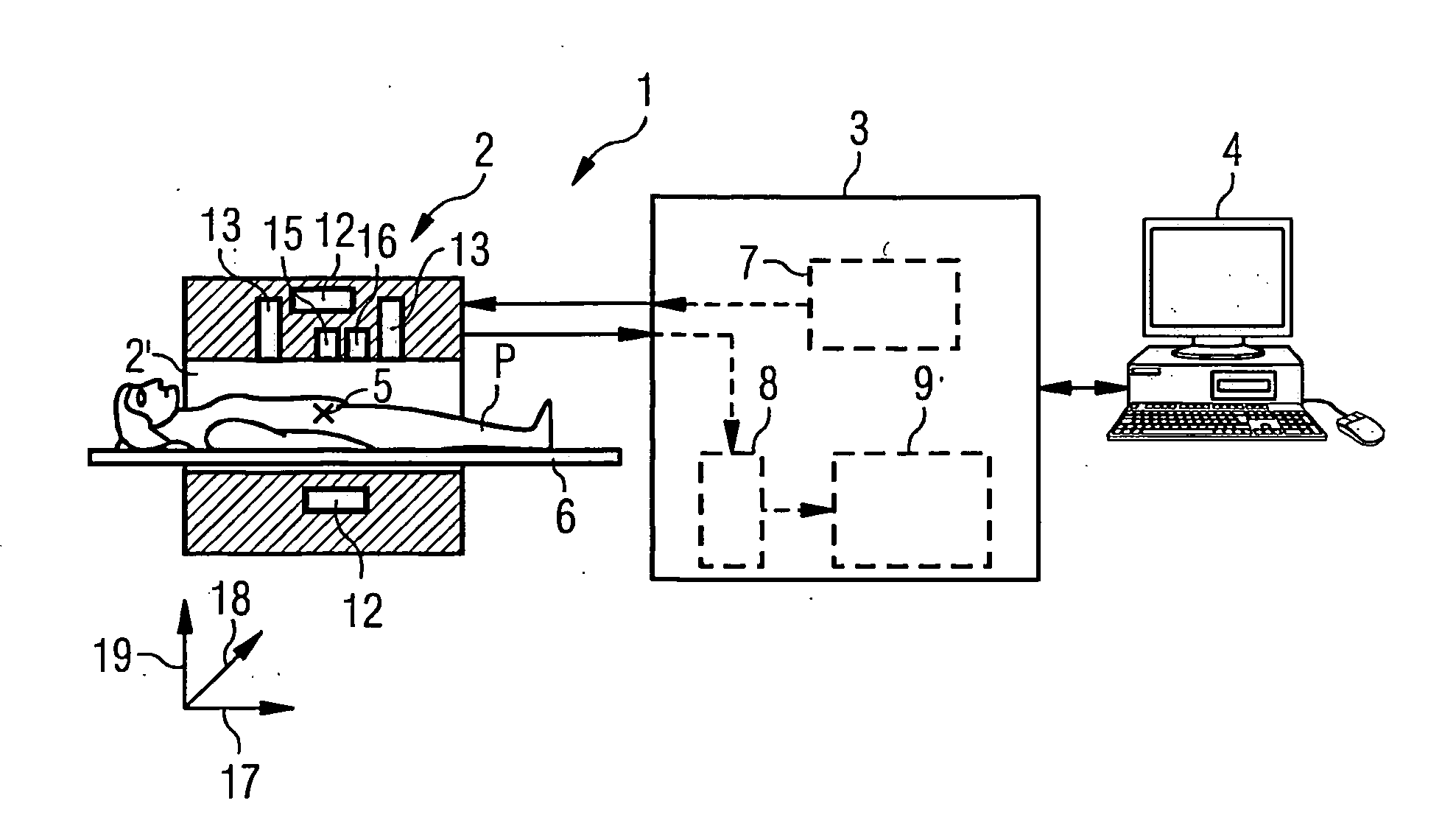
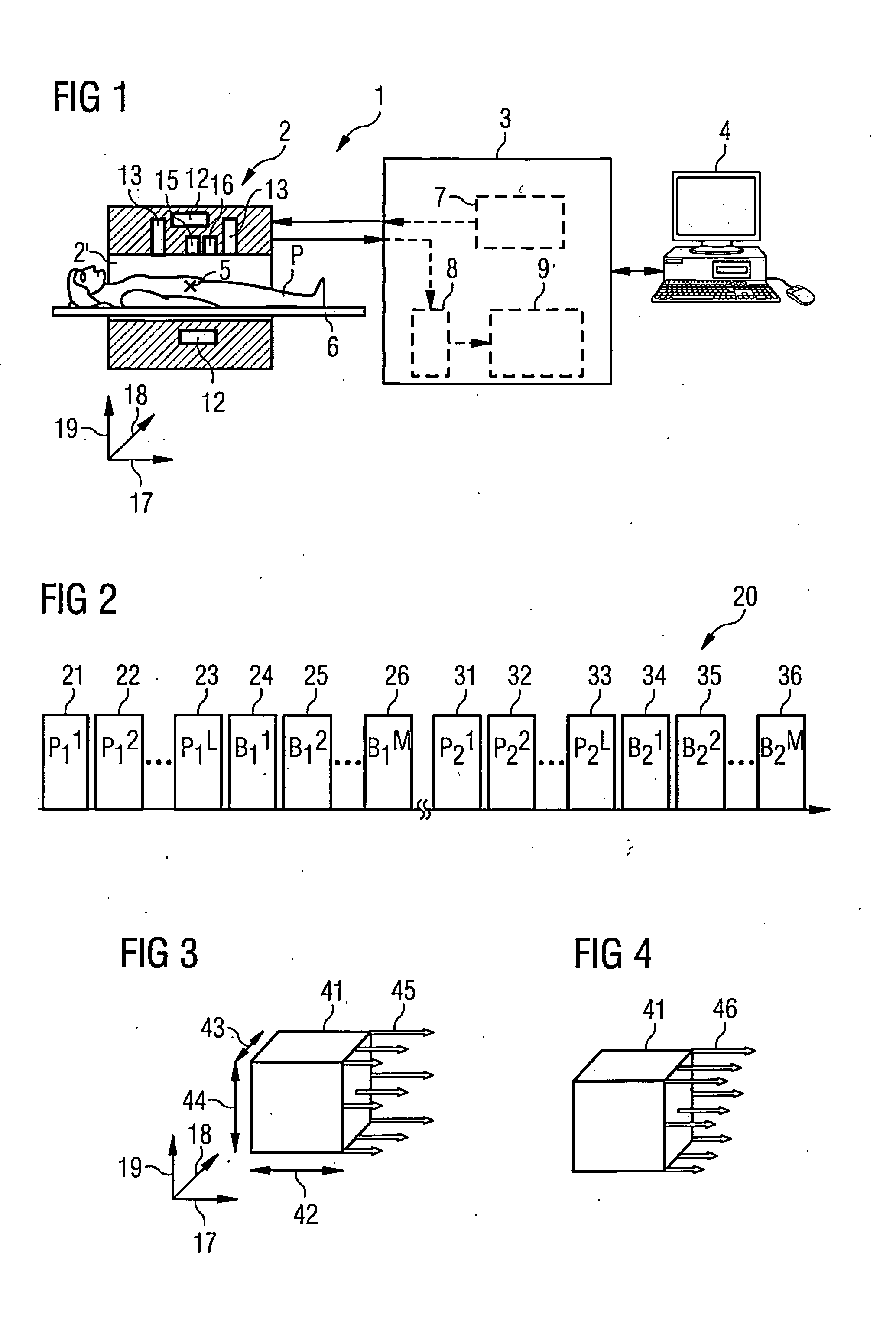
[0070]FIG. 1 is a schematic representation of an apparatus 1 for MR imaging. The apparatus 1 includes a data acquisition unit 2, commonly called a scanner. An examination subject P can be driven into a hollow space 2a of the scanner 2. A region of interest of the examination subject P can be positioned at an isocenter 5 via suitable positioning of a support device 6. The scanner 2 has multiple coil components / systems in order to generate a basic magnetic field (BO field) to align nuclear spins in the patient P, gradient fields, and radio-frequency (RF) pulses. The operation of the scanner 2 is controlled by a computer 3. The computer 3 can include a controller 7, an acquisition unit 8 to receive spin signals acquired with reception coils, and an evaluation computer 9 to process the acquired spin signals. A suitable user interface or an additional computer 4 can be provided in order to control the operation of the scanner 2 and / or to further process acquired data.

[0071]In addition to...


PUM


Abstract

In a method and apparatus for magnetic resonance (MR) imaging, a magnetization of nuclear spins in a subject is prepared in multiple preparation modules of an acquisition sequence. MR signals are acquired with at least one imaging module of the sequence. Spoiler gradient fields are generated in the multiple preparation modules in order to affect a transverse magnetization of the spins. The spoiler gradient fields that are applied in at least two different preparation modules are spatially varied along different directions. Spoiler gradient moments of the spoiler gradient fields are selected so that, for at least one of three orthogonal spatial directions, a weighted sum of the spoiler gradient moments that are applied along this spatial direction satisfies a threshold condition.

Description

BACKGROUND OF THE INVENTION[0001]1. Field of the Invention[0002]The invention concerns a method and an apparatus for magnetic resonance imaging. In particular, the invention concerns such a method and such an apparatus in which a transverse magnetization can be specifically dephased using one or more gradient pulses in preparation of the magnetization.[0003]2. Description of the Prior Art[0004]Magnetic resonance (MR) imaging is an imaging modality that is used for examination and diagnosis in many fields of medicine. It based on the physical effect of nuclear magnetic resonance. To acquire MR signals, a defined longitudinal magnetization is generated or suppressed in a preparation module or multiple preparation modules of an imaging sequence. The dynamics of the nuclear spins can be observed after radiating radio-frequency pulses.[0005]In MR imaging, the suppression of unwanted signal contributions is gaining high importance. For example, in the clinical routine, signal contribution...

Claims


Application Information

Patent Timeline
Patent Type & Authority Applications(United States)
IPC IPC(8): G01R33/56G01R33/38
CPCG01R33/5607G01R33/4838
Inventor FEIWEIER, THORSTENKUEHN, BERND
Owner SIEMENS HEALTHCARE GMBH
Why Eureka
Try Eureka