Video-based warning system for a vehicle

a video-based warning and vehicle technology, applied in the field of video-based warning systems for vehicles, can solve the problems of blind spot detection, reduced degree of freedom of possible motion patterns, and inability to provide full rearview to detect objects approaching from behind, so as to increase the reliability of the system and avoid unnecessary processing.

Inactive Publication Date: 2013-04-11
HONDA RES INST EUROPE
View PDF7 Cites 26 Cited by
  • Summary
  • Abstract
  • Description
  • Claims
  • Application Information

AI Technical Summary

Benefits of technology

[0028]For a rear-facing camera, while the vehicle is moving forwards, a contracting motion of pixels in two consecutive video images is caused. In other words, all pixels move towards a so called focus of contraction (FOC). The line that crosses the FOC and the two points describing the positions of a moving pixel is also called epipolar line. The above is only valid for pixels that correspond to static elements in the real world. Other elements, like moving objects, cause motion that is not pointing to the FOC. Therefore a separation of the motions of stationary objects and moving objects is possible.
[0029]Preferably, the computing unit is adapted to disregard motion information of pixels, which do not follow one of the contracting and expanding motions obtained during the motion segmentation. The reliability of the system can be increased, and unnecessary processing can be avoided.

Problems solved by technology

Blind spot detection, however, provides only a limited scenario, since it mainly senses to the sides of the vehicle.
This reduces the degrees of freedom of possible motion patterns.
In particular a full rear-view cannot be provided to detect objects approaching from behind.
Since the above systems have been designed specifically for cars, none of the systems can cope with a leaning of the vehicle, as it occurs for example for a motorcycle when driving though curves.

Method used


Image

  • Video-based warning system for a vehicle
  • Video-based warning system for a vehicle
  • Video-based warning system for a vehicle

Examples


Embodiment Construction

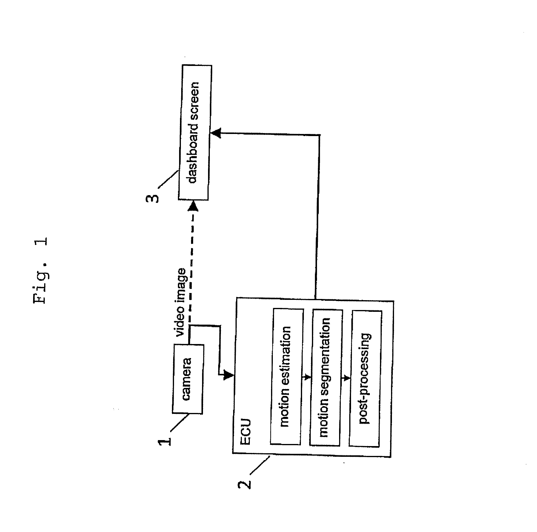
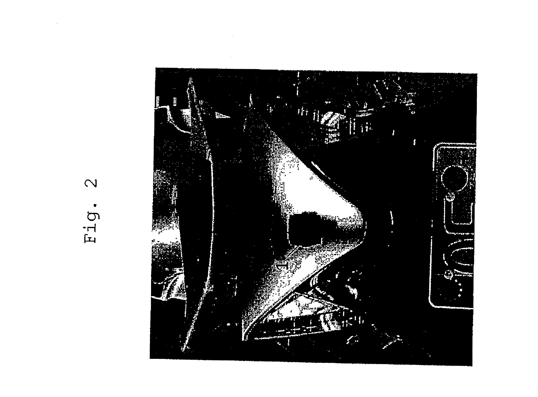
[0046]FIG. 1 shows the main parts of the warning system of the present invention. The warning system is comprised of a camera 1 with an image sensor. The image sensor of the camera 1 can be a conventional CMOS or CCD, but the camera is not limited to any specific type. The camera 1 is preferably a rear-facing or rear-view camera. Therefore it is preferably attached at the rear or back of the vehicle (inside or outside). As an example, FIG. 2 shows a rear-facing camera 1 attached to the back of a motorcycle. The camera 1 mounting should not interfere with other functions like the backlights, luggage carrier, side bags etc. of the vehicle. Also the camera image should not be negatively affected by the backlights of the motorcycle. However, the camera should be well protected against dirt and water. This could be achieved by a casing or a shield that keeps dirt, dust and water out of the camera 1.

[0047]The camera 1 has an output that delivers a video image signal to a computing unit 2....


PUM


Abstract

The present invention proposes a warning system that can be implemented in any kind of vehicle, in order to efficiently detect moving objects. The system utilizes at least one camera for a continuous imaging of the surroundings of the vehicle. Thereby, moving objects can be monitored. A computing unit is programmed to estimate a motion of any moving object based on a pixel motion in the camera image. If a dangerously moving object is detected, a warning unit can be used for issuing a warning signal. To take such a decision, the estimated motion of at least one of the moving objects can be correlated or compared to predetermined motion patterns.

Description

BACKGROUND OF THE INVENTION[0001]The present invention describes a warning system and a warning method for a vehicle like a car, a truck or a motorcycle / scooter. The warning system is used for detecting moving objects. To this end the warning system uses a camera to sense the surroundings of the vehicle, and a computing unit to determine moving objects form the camera image. The present invention is directed in particular to monitoring the rear of a motorcycle for detecting approaching objects that might pose a risk to the driver.STATE OF THE ART[0002]A prototype with a similar function but with a radar system instead of an optical camera to sense moving objects has been built recently (see ‘Koehlen et al., Erster Radarbasierter Spurwechselassistent fuer motorisierte Zweiraeder, FAS 2011-7th workshop on driver assistance systems, TU Braunschweig). However, one conclusion from this research project was that a different sensor, which is smaller and cheaper than a radar system is prefe...

Claims


Application Information

Patent Timeline
Patent Type & Authority Applications(United States)
IPC IPC(8): B60Q1/00H04N7/18
CPCG06T7/2006B60W50/14G08G1/166G06T2207/30261B60W2420/42G06T7/215
Inventor DEIGMOLLER, JORGEGGERT, JULIANJANSSEN, HERBERTFUCHS, OLIVER
Owner HONDA RES INST EUROPE
Why Eureka
Try Eureka