Hydraulic transmission system for zero-turn vehicle

a transmission system and zero-turn technology, applied in the direction of fluid couplings, couplings, transportation and packaging, etc., can solve the problems of insufficient fluid flow in the high-pressure pipe to operate smoothly the hydraulic actuator and cool the entire hydraulic transmission system. , to achieve the effect of promoting fluid circulation

Active Publication Date: 2013-04-18
KANZAKI KOKYUKOKI MFG
View PDF6 Cites 1 Cited by
  • Summary
  • Abstract
  • Description
  • Claims
  • Application Information

AI Technical Summary

Benefits of technology

[0012]An object of the invention is to provide an effective and economical hydraulic fluid circulation system for cooling the hydraulic transmission system, which especially needs no additional charge pump for making the flow of fluid from one transaxle to the other transaxle, wherein even if the hydraulic fluid circulation system is utilized for operating a hydraulic actuator, the expected efficiency of cooling the entire hydraulic transmission system by the cooling system can be kept while ensuring expectedly smooth operability of the hydraulic actuator.
[0014]Therefore, part of the fluid delivered from the charge pump of the first transaxle is supplied to the charge pressure regulation valve, and the fluid released from the charge pressure regulation valve is fully supplied to the first pipe without branching, thereby efficiently cooling the entire hydraulic transmission system with no additional charge pump increasing costs. Further, if the first pipe is provided on any intermediate portion thereof with no hydraulic actuator resisting the flow of fluid in the first pipe, the first pipe further surely makes the flow of fluid therein from the first port of the transaxle to the first port of the second transaxle.
[0018]Therefore, the hydraulic actuator does not interrupt the flow of fluid in the first pipe, thereby further ensuring the sufficient flow of fluid in the first pipe for cooling the entire hydraulic transmission system. The operation of the hydraulic actuator is prevented from causing loss of hydraulic fluid because it can use overflowing fluid of the fluid sump of the second transaxle that is liable to overflow because fluid delivered from the charge pump of the second transaxle as well as fluid delivered from the charge pump of the first transaxle via the first pipe is drained to the fluid sump of the second transaxle. Further, if the operated hydraulic actuator reaches its limit position so as to interrupt the flow of fluid therethrough from the third pipe to the fourth pipe, the actuator pressure regulation valve regulates the pressure of fluid in the charge passage at the downstream side thereof in response to an unexpected hydraulic pressure applied from the third port to the fluid extraction passage according to the interruption of the flow of fluid between the third and fourth pipes.
[0020]Therefore, part of the fluid delivered from the charge pump of the first transaxle is passed through the first orifice and is supplied to the first pipe, thereby cooling the entire hydraulic transmission system with no additional charge pump increasing costs. If the first pipe is provided on any intermediate portion thereof with no hydraulic actuator resisting the flow of fluid in the first pipe, the first pipe further surely makes the flow of fluid therein from the first port of the transaxle to the first port of the second transaxle. Even if a hydraulic actuator is disposed on an intermediate portion of the first pipe so as to resist the flow of fluid in the first pipe, and the moved hydraulic actuator reaches a limit position of its movement, the first orifice resists backpressure of fluid from the hydraulic actuator toward the charge passage of the first transaxle, thereby preventing hydraulic pressure in the charge passage of the first transaxle from being suddenly increased by the backpressure from the hydraulic actuator on the first pipe.
[0024]Therefore, the part of the fluid delivered from the charge pump of the first transaxle and passed through the first orifice is fully supplied to the first pipe without branching, thereby further efficiently cooling the entire hydraulic transmission system with no additional charge pump increasing costs. If the first pipe is provided on any intermediate portion thereof with no hydraulic actuator resisting the flow of fluid in the first pipe, the first pipe further makes sure fluid flows therein from the first port of the transaxle to the first port of the second transaxle.
[0030]Therefore, while the first pipe interposed between the first ports of the first and second transaxles makes fluid flow from the first transaxle to the second transaxle, the third pipe interposed between the third ports of the first and second transaxles makes fluid flow from the second transaxle to the first transaxle, thereby promoting fluid circulation between the first and second transaxles for cooling the hydraulic transmission system. The flow of fluid in the third pipe from the second transaxle to the first transaxle is also used for operating the second hydraulic actuator. The flow of fluid in the third pipe from the third port of the second transaxle to the third port of the first transaxle is ensured without interruption so as to prevent the second orifice from being unexpectedly pressurized by interruption of the flow of fluid in the third pipe because it is allowed to pass the second hydraulic actuator or the second switching valve regardless of whether the second switching valve is opened or closed. In this way, the fluid circulation system for the hydraulic transmission system is utilized for operating the two hydraulic actuators.

Problems solved by technology

However, the pipes must be expensive high pressure pipes, such as metal pipes.
On the other hand, the pipe interposed between the ports on the lower portions of the casings of the right and left transaxles must be an expensive high pressure pipe because it must bear against forcible flow of hydraulic fluid from one casing to the other casing.
However, it seems that, regardless of whether or not the hydraulic actuator reaches the limit position, fluid released from the charge pressure regulation valve in the first transaxle is liable to flow into the drain passage in the first transaxle rather than to flow into the high pressure pipe having the hydraulic actuator resisting the flow of fluid in the high pressure pipe, so that the flow of fluid in the high pressure pipe may be insufficient to smoothly operate the hydraulic actuator and to cool the entire hydraulic transmission system as expected.
The high pressure pipe is provided on an intermediate portion thereof with no hydraulic actuator, however, with an additional charge pump to make sure fluid flows from one transaxle to the other transaxle, thereby increasing costs.

Method used


Image

  • Hydraulic transmission system for zero-turn vehicle
  • Hydraulic transmission system for zero-turn vehicle
  • Hydraulic transmission system for zero-turn vehicle

Examples


Embodiment Construction

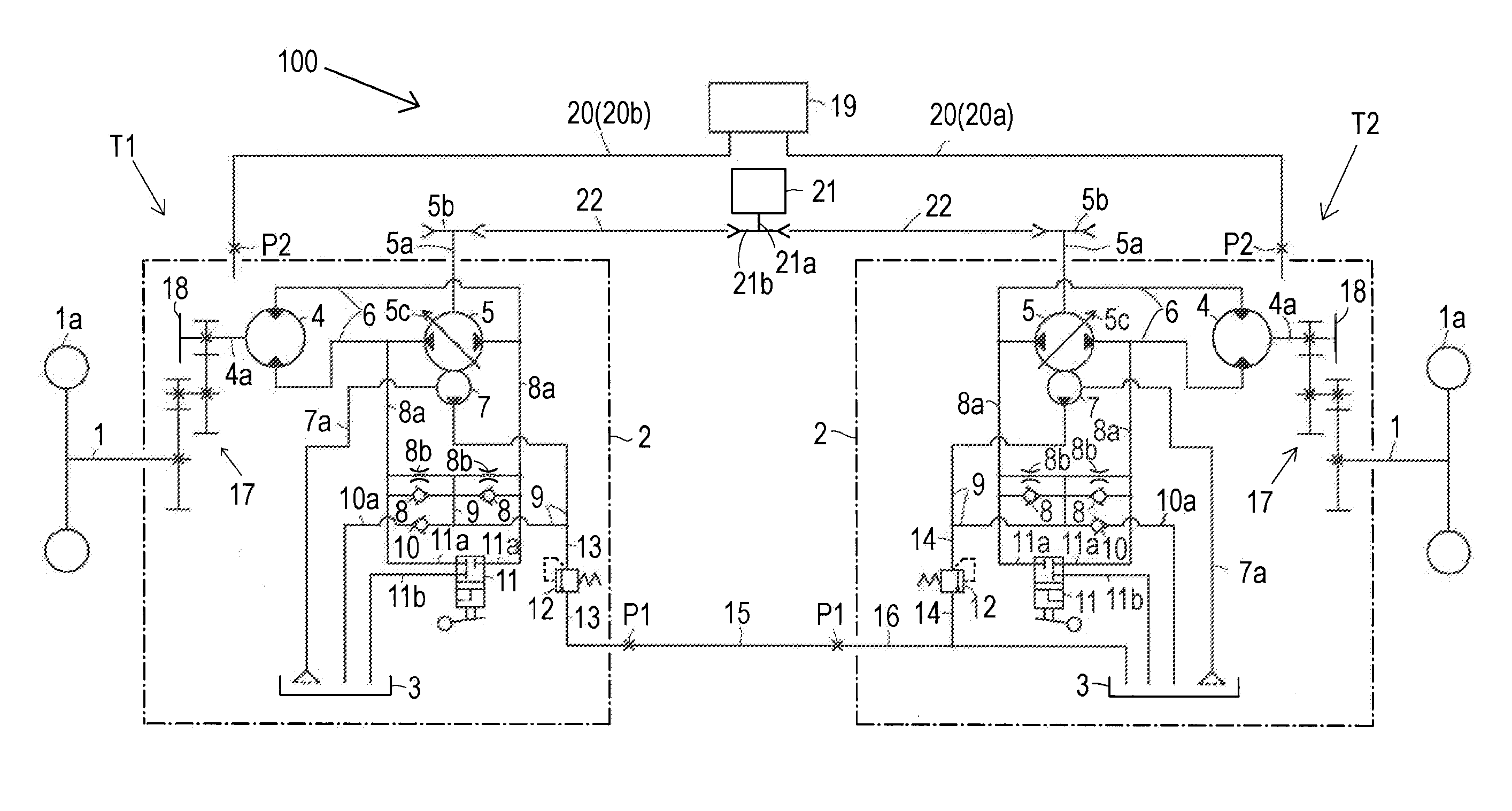
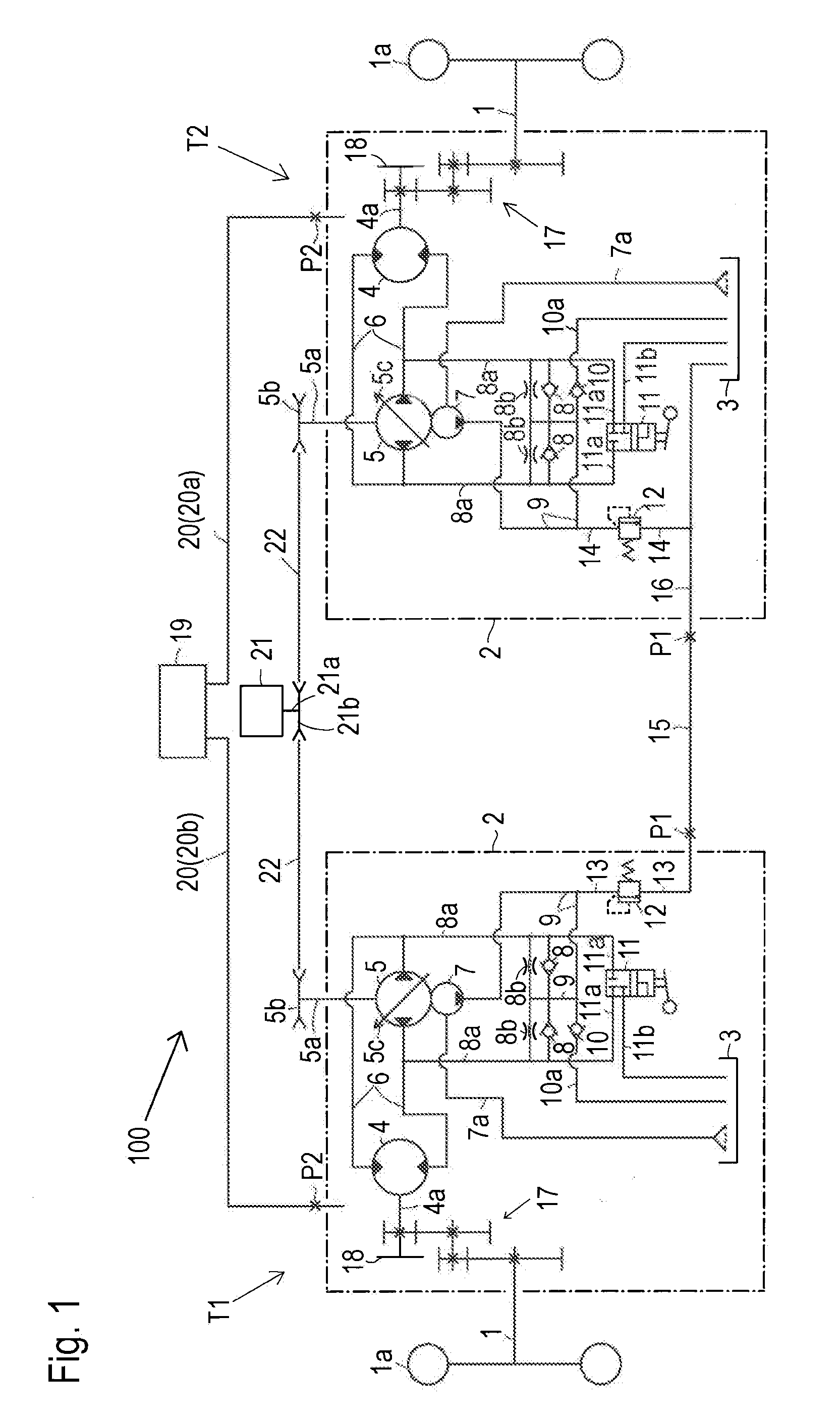
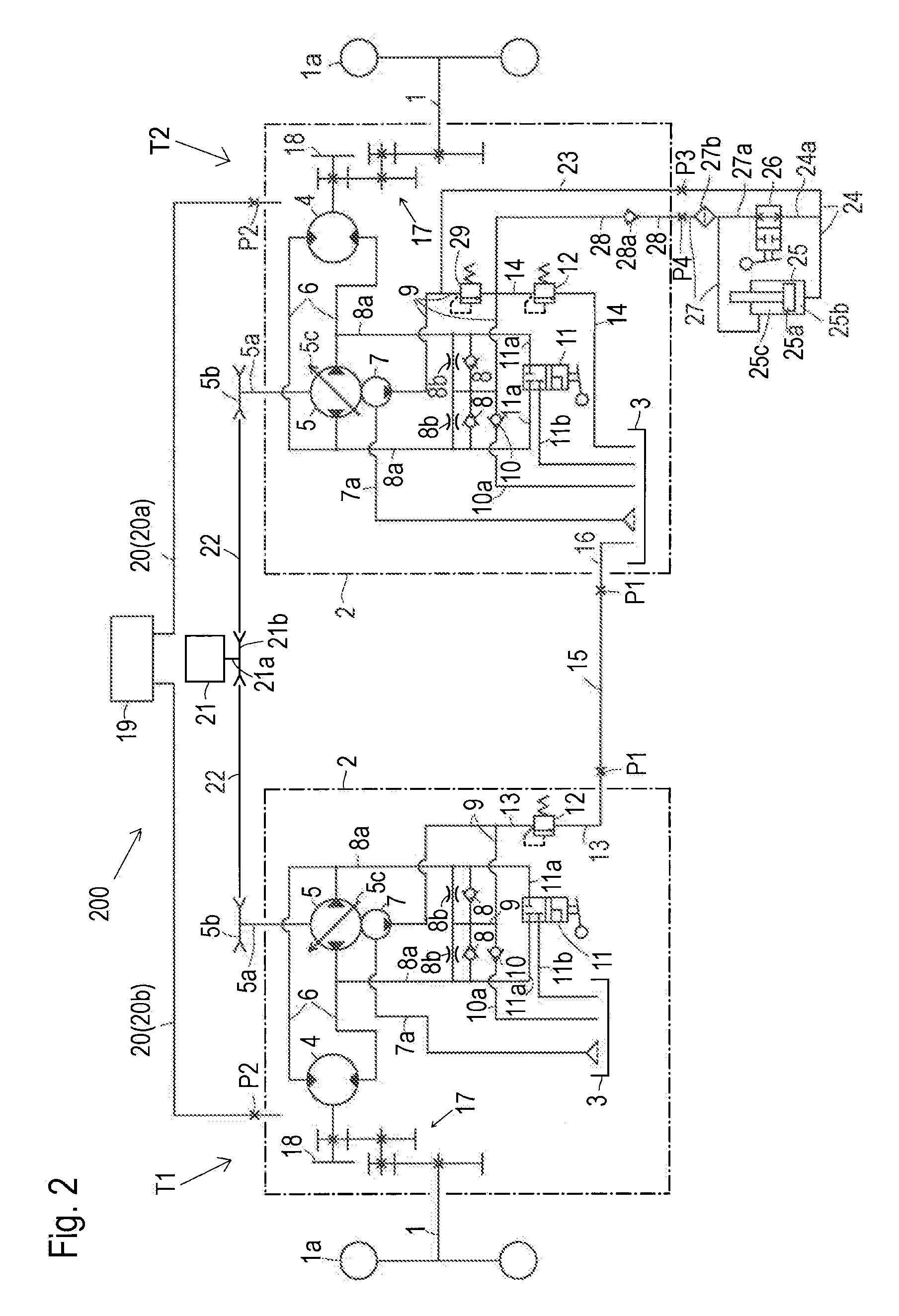
[0039]Referring to FIGS. 1 to 5, each of hydraulic transmission systems 100, 200, 300, 400 and 500 is adaptable as a transmission system for a zero-turn vehicle such as a lawn mower.

[0040]First, a common structure to hydraulic transmission systems 100, 200, 300, 400 and 500 will be described with reference to FIGS. 1 to 5. Each of hydraulic transmission system 100, 200, 300 and 400 includes a pair of transaxles T1 and T2. Each of transaxles T1 and T2 includes an axle 1 and a casing 2 supporting axle 1. Transaxles T1 and T2 are adapted in a zero-turn vehicle as right and left transaxles so that axles 1 supported by casings 2 of respective transaxles T1 and T2 serve as right and left axles 1 for supporting right and left drive wheels 1a of the vehicle. As detailed later, each of first and second transaxles T1 and T2 has an HST and a charge pump for charging fluid to the HST, first transaxle T1 is defined as draining fluid delivered from its own charge pump to a fluid sump of second tr...


PUM


Abstract

A hydraulic transmission system for a zero-turn vehicle, comprises first and second transaxles each of which includes an axle, a casing supporting the axle, a fluid sump provided in the casing, first and second ports provided on the casing and opened outward from the casing, an HST circuit, a charge pump disposed in the casing, and a charge passage disposed in the casing to supply the HST circuit with fluid delivered from the charge pump. A first pipe connects the first ports of the transaxles, thereby making the flow of fluid from the charge pump of the first transaxle to the fluid sump of the second transaxle. A second pipe connects the second ports of the transaxles, whereby overflowing fluid of the fluid sump of the second transaxle is released to the fluid sump of the first transaxle via the second pipe.

Description

BACKGROUND OF THE INVENTION[0001]1. Field of the Invention[0002]The present invention relates to a hydraulic transmission system that includes right and left hydrostatic transaxles supporting respective right and left axles so as to be applicable to a zero-turn vehicle, such as a lawn mower.[0003]2. Related Art[0004]US 2009 / 0301076 A1 teaches a lawn mower, serving as a typical zero-turn working vehicle, which is equipped with a hydraulic transmission system including right and left hydrostatic transaxles (integral hydrostatic transaxles, i.e., “IHT”s) supporting respective right and left axles, so that the right and left transaxles are available to differentially control the right and left axles, thereby enabling zero-turn of the vehicle. Each of the transaxles includes a casing that incorporates a hydrostatic stepless transmission (HST) and supports the corresponding axle. The HST includes a hydraulic pump, a hydraulic motor for driving the corresponding axle, a hydraulic circuit (...

Claims


Application Information

Patent Timeline
Patent Type & Authority Applications(United States)
IPC IPC(8): F15B13/00
CPCF16H61/4139F15B7/006B60Y2200/223F15B2211/7058F15B2211/20546F15B2211/613F15B2211/20523
Inventor KITA, TSUYOSHIIWAKI, KOJI
Owner KANZAKI KOKYUKOKI MFG
Why Eureka
Try Eureka