Mass distribution measuring method and mass distribution measuring apparatus

a mass distribution and measuring method technology, applied in the direction of mass spectrometers, dispersed particle separation, separation processes, etc., can solve the problems of noticeably influence the strength of the beam within the beam, and the inability to accurately measure the mass distribution of this region, etc., to reduce the damage to an organic sample, reduce the damage of the sample, and increase the uncertainty of the secondary ion generation time

Inactive Publication Date: 2013-04-18
CANON KK
View PDF1 Cites 7 Cited by
  • Summary
  • Abstract
  • Description
  • Claims
  • Application Information

AI Technical Summary

Benefits of technology

[0026]Any ionizing method can be used herein as far as it causes an energy beam to be incident on a sample surface. The ionizing beam is selected from ions, a laser light, neutral particles, electrons, or the like depending on analyzing methods. At this time, a method such as MALDI may be used. It should be noted that, when a mass spectrometry method that provides high spatial resolution is used, an influence of a shadow due to an irregularity on a substrate is particularly emphasized. Therefore, an advantage of the present invention can be more noticeable in an SIMS method of using primary ions as an ionizing beam. The method of causing the ionizing beam to be incident on the sample surface is not limited, and any method may be used. For a scanning type, a focused ionizing beam is irradiated, and for a projection type, an ionizing beam is irradiated to a wide region on a sample. The projection type provides higher spatial resolution than the scanning type, and thus an advantage of the present invention is more noticeable. In the projection type, further, a configuration of a mass spectrometry section can be simplified, and thus it has a high affinity for the present invention, and therefore it can be more favorably used.
[0027]The sample 3 is in a solid phase, and it may include an organic compound, an inorganic compound, or a biological sample. When MALDI is used, an aromatic organic compound or the like that supports ionization may be added to the sample surface and crystallized. The sample is secured on the substrate 2 having a substantially flat surface.
[0028]The mass spectrometry method is not particularly limited. Mass spectrometry methods of various types such as time-of-flight, magnetic deflection, quadrupole, ion trap, or Fourier transform ion cyclotron resonance may be used. When a projection type ion detection is adopted, a time-of-flight mass spectrometry method can be used to simultaneously record a detection time and a detection position of ions.
[0029]In one embodiment of the present invention as described herein, primary ions are used as an ionizing beam, and a time-of-flight mass spectrometry method and a projection type two-dimensional ion detection method are adopted. It should be noted that the descriptions below are not intended to limit the present invention to this configuration.
[0030]FIG. 1 is a schematic view illustrating an apparatus for carrying out the mass distribution measuring method according to this embodiment. An ionizing beam is emitted for an extremely short time in an emitting direction from the ionizing beam irradiation unit 1, and then irradiated to the sample 3 on the substrate 2. In other words, the ionizing beam is emitted in a pulse shape. A long pulse width increases uncertainty of a secondary ion generation time, and reduces mass resolution. Thus, for example, when an ion beam is used, the pulse can be set to 1 ns or less. The ionizing beam is incident on a surface of the substrate 2 or the sample 3 obliquely of the surface of the substrate 2.
[0031]As primary ions, liquid metal ions such as Bi+ and Ga+, metal cluster ions such as Bi3+ and Au3+, or gas cluster ions such as Ar may be used. Use of the cluster ions can reduce damage to an organic sample.

Problems solved by technology

In the conventional imaging mass spectrometer, depending on an incident angle of an ionizing beam on the substrate surface, there appears, around the irregularity, a shadow to which no ionizing beam is irradiated, and mass distribution of this region cannot be accurately measured.
Also, when an ionizing beam having a large diameter is used as in the mass spectrometer described in the Japanese Patent Application Laid-Open No. 2007-157353, non-uniformity of beam strength within the beam noticeably influences measurement of mass distribution in addition to the above problem.

Method used


Image

  • Mass distribution measuring method and mass distribution measuring apparatus
  • Mass distribution measuring method and mass distribution measuring apparatus
  • Mass distribution measuring method and mass distribution measuring apparatus

Examples


example 1

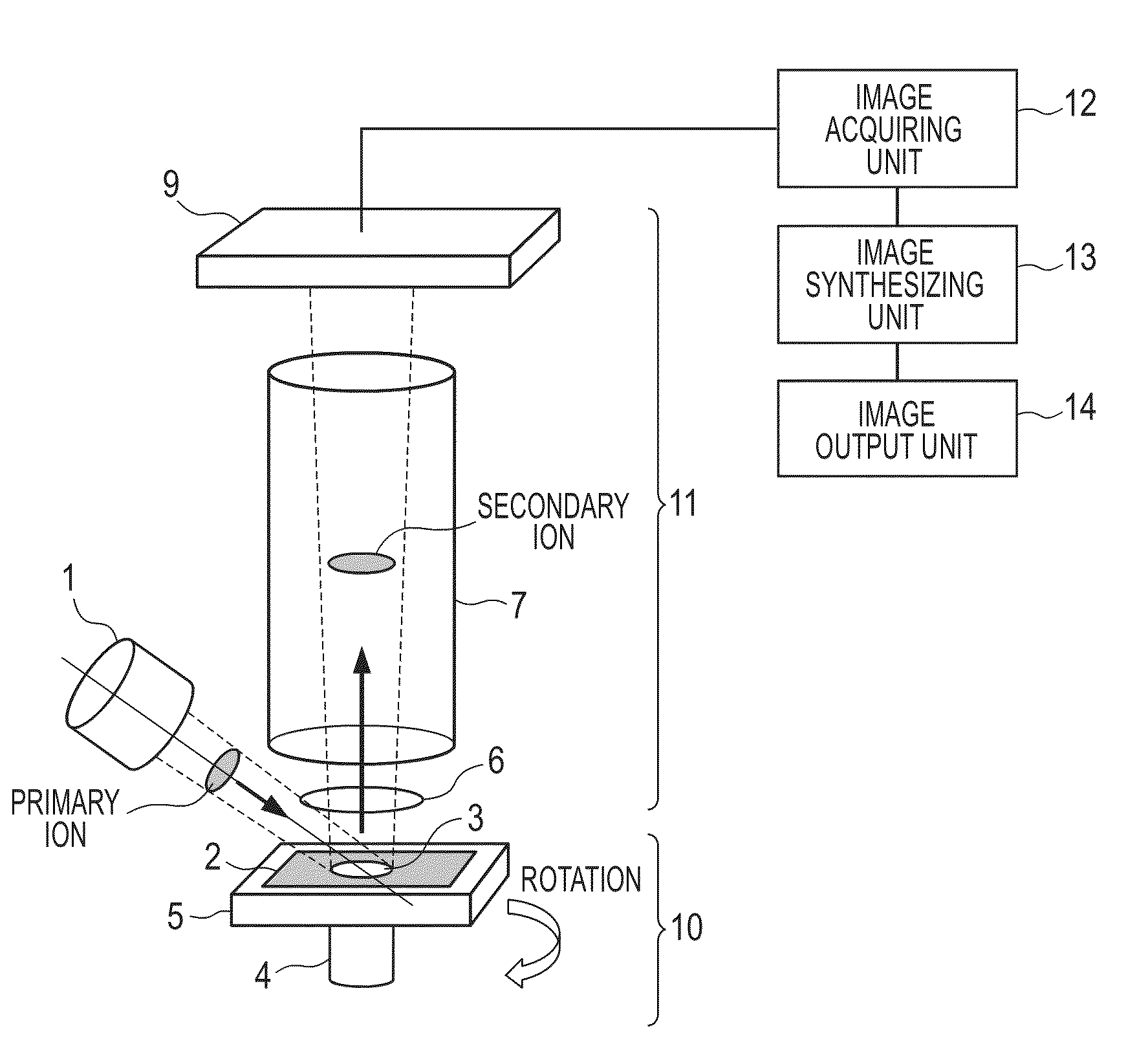
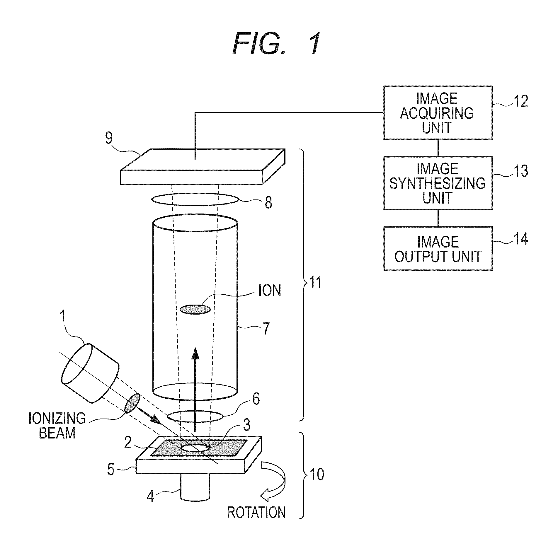
[0067]With reference to FIGS. 5 and 6, a first example according to the present invention will be described. FIG. 5 is a schematic view of a configuration of an apparatus for carrying out the method of the present invention in this example.

[0068]A conductive substrate is used as a substrate 2, and a protrusion pattern that can specify a direction is formed on the substrate 2 using a photolithography process or the like. A sample 3 such as a biological sample holding a thin cell form is placed on the substrate 2.

[0069]A direction changing unit 10 includes a rotation mechanism 4, and a translation mechanism 5. The translation mechanism 5 is placed on the rotation mechanism 4. The translation mechanism 5 is displaceable in a direction perpendicular to a rotation axis. The substrate 2 is placed on the translation mechanism 5 so that a plane of the substrate 2 is perpendicular to a rotation axis of the rotation mechanism 4.

[0070]Primary ions are used as a beam output by an ionizing beam ...

example 2

[0076]A second example according to the present invention will be described with reference to FIGS. 7A to 7G. This example is different from Example 1 in an image synthesizing process. An apparatus configuration used in this example is the same as in Example 1, and thus descriptions thereof will be omitted.

[0077]In this example, the substrate 2 is rotated every 90° to apply primary ion beams from a total of four directions. The rotation angle of the substrate 2 can be arbitrarily set, provided that a pair of angles can be set so that measurement is performed at 180° different rotation angles. Specifically, when the substrate rotation angle is set as θ (degree), a pair of θ=0 and 180, and a pair of θ=90 and 270 are set.

[0078]The mass distribution measuring apparatus perform a plurality of times of measurements in each of the plurality of rotation directions, and stores data on an ion detection position and a mass-to-charge ratio. After a series of measurement for each direction is co...

example 3

[0089]This example is partially different from Example 2 in an image synthesizing process. An apparatus configuration is the same as in Example 2, and thus descriptions thereof will be omitted. In this example, mass distribution images having different incident angles θ of primary ions are successively compared to form a synthesized image.

[0090]To apply primary ions from three directions, θ=0, 120, 240 (degrees) are set. For each θ, a mass distribution image is acquired and subjected to rotational transform to form r-F0(θ).

[0091]First, r-F0(θ) and r-F0(120) are compared. A comparing method is basically the same as comparison between r-F0(0) and r-F0(180) in Example 2. The comparison result is stored in a first reference table. A synthesized image CFm1 is output based on the first reference table.

[0092]Then, the synthesized images CFm1 and r-F0(240) are compared as described above, and the comparison result is stored in a second reference table. A synthesized image CFm is output base...


PUM


Abstract

To provide a method that reduces an influence of dependence of an ionizing beam in an incident direction or uneven irradiation to a sample on a result of mass spectrometry, and can measure mass distribution with high reliability. A mass distribution measuring method according to the present invention includes: changing a direction of irradiating the ionizing beam to a sample surface; acquiring a plurality of mass distribution images in a plurality of incident directions; performing image transform of the mass distribution images according to an angle formed by an incident direction of the ionizing beam and a substrate surface; synthesizing the plurality of transformed images; and outputting the synthesized mass distribution images.

Description

BACKGROUND OF THE INVENTION[0001]1. Field of the Invention[0002]The present invention relates to a method for ionizing a substance on a sample, performing mass spectrometry of the substance, and imaging and outputting in-plane distribution of the substance, and an apparatus used therefor.[0003]2. Description of the Related Art[0004]As an analyzing method for comprehensively visualizing distribution information of many substances that constitute body tissue, an imaging mass spectrometry method has been developed, for which a mass spectrometry method is applied. In a mass spectrometry method, a sample is ionized by irradiating a laser light or primary ions and then separated according to a mass-to-charge ratio to obtain a spectrum including the mass-to-charge ratio and detection strength therefor. A sample surface can be subjected to mass spectrometry two-dimensionally so as to obtain two-dimensional distribution of detection strength of a substance corresponding to each mass-to-charg...

Claims


Application Information

Patent Timeline
Patent Type & Authority Applications(United States)
IPC IPC(8): H01J49/26
CPCH01J49/00H01J49/0004H01J49/142
Inventor KYOGAKU, MASAFUMITANJI, KOICHI
Owner CANON KK
Why Eureka
Try Eureka