Sensor readout with redundancy-checking

a technology of readout circuit and readout circuit, which is applied in the direction of electrical/magnetically converting sensor output, instruments, force measurement, etc., can solve the problems of increasing the overall cost, reducing a single sensor already showing internal redundancy, etc. problem, to achieve the effect of increasing the reliability of the overall sensor system, maximizing and little prior-art in exploiting the internal redundancy of the sensor

Active Publication Date: 2013-04-18
MELEXIS TECH NV
View PDF2 Cites 19 Cited by
  • Summary
  • Abstract
  • Description
  • Claims
  • Application Information

AI Technical Summary

Benefits of technology

[0011]It is an object of embodiments of the present invention to provide good difference measurement circuits and methods for operating them.
[0013]In a first aspect, the present invention provides a difference measurement circuit comprising a first port and a second port for connection to a first set of nodes and a second set of nodes of a sensor unit. The difference measurement circuit further comprises switching units for switching excitation signals emanating from excitation nodes from being applied to the first set of nodes via the first port to being applied to the second set of nodes via the second port and for switching differential measurement signals measured at sensing nodes from being obtained from the second set of nodes via the second port to being obtained from the first set of nodes via the first port. The difference measurement circuit furthermore comprises redundancy testing circuitry for evaluating the similarity or deviation between measurement signals obtained in different states of the switching units. It is an advantage of a difference measurement circuit according to embodiments of the present invention that dynamic reconfiguration of the sensor unit, for example an impedance bridge or any other sensor unit having sufficient symmetry for being reconfigurable, allows testing whether readout values in different configurations obtained at different sample instants are close enough to one another, thus performing a redundancy-test.
[0017]A difference measurement circuit according to embodiments of the present invention may furthermore comprise an AD converter for converting an analog measurement signal into a digital signal. This allows to perform processing of the measurement signal in the digital domain; which allows more advanced processing techniques to be used.
[0020]Alternatively, in a difference measurement circuit according to embodiments of the present invention, both the first and second excitation sources may be independent sources of nominally equal value, the excitation circuitry further comprising at least one adaptable source specifically configured for injecting, i.e. sourcing or draining, a nominally equal amount of current to both sensing nodes. The excitation circuitry may then further be provided with a feedback circuit for controlling the at least one adaptable source for stabilizing the linear combination of the voltages at excitation nodes and / or at sensing nodes to a predetermined value.
[0022]In embodiments of a difference measurement circuit according to embodiments of the present invention, one of the first or second current sources may be a fixed current source, and the other one of the first or second current sources may be an adaptable current source, the excitation circuitry being provided with a feedback loop for making equal the current provided by both current sources. In alternative embodiments of a difference measurement circuit according to embodiments of the present invention, both the first and second current sources may be fixed current sources of nominally equal value, and the excitation circuitry may furthermore being provided with at least one adaptable current source that bypasses the bridge and that is settable to a value which corrects the inevitable small current differences between the fixed sources. These embodiments provide common mode regulation of the bridge.
[0025]In particular embodiments of the present invention, a difference measurement circuit may furthermore comprise two additional switching units for changing the sign of the excitation and measurement signals. In combination with the switching units as provided in a basic embodiment of a difference measurement circuit according to embodiments of the present invention, this allows rotation and flip-over of the bridge. This, in turn, allows to carry out a full redundancy test of a sensor unit coupled to the difference measurement circuit according to embodiments of the present invention. According to an alternative embodiment of this approach, the different switching units may be merged into a larger unit which realizes the same connectivity possibilities to allow rotation and flip-over of the bridge.

Problems solved by technology

Unfortunately, introducing redundancy at the level of complete sensors significantly increases the overall cost.
In many cases, even a single sensor already exhibits some internal redundancy.
There is little prior-art on exploiting the internal redundancy of a sensor for increasing the reliability of an overall sensor system.
However, it is a disadvantage of the solution proposed in this document that it is not a “complete” test, which can detect all mismatch conditions.
It is further assumed that R4 and R1 are mismatched in the same way, for instance because the mismatch has a common cause (e.g., irregularity in a membrane which provides a same mismatch to the resistances, a large temperature gradient over the sensor).

Method used


Image

  • Sensor readout with redundancy-checking
  • Sensor readout with redundancy-checking
  • Sensor readout with redundancy-checking

Examples


Embodiment Construction

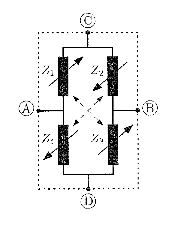
[0060]An impedance bridge configuration is a very general topology for a sensor unit, including resistive bridges, capacitive bridges or bridges comprising other types of frequency-dependent bridge elements. In FIG. 1, a general impedance bridge is illustrated, comprising four impedances (Z1, Z2, Z3, Z4). It is assumed that the sensor unit has internal redundancy, and that the pairs Z1|Z3 and Z2|Z4 are matched under normal conditions. Apart from this matching property, the impedances are considered general. This includes resistive bridges (FIG. 5), capacitive bridges (FIG. 6), etc. For resistive bridges, the impedance relation becomes Zi=Ri, with Ri the variable resistances of the sensor unit. For capacitive bridges, the impedance relation becomes

Zi=1jωCi,

where Ci are the variable capacitances of the sensor unit. Also inductance-based bridges (having impedances Zi=jωL1) can be included in embodiments of the present invention (not illustrated in the drawings). In its most general for...


PUM


Abstract

A difference measurement circuit including a first port and a second port for connection to a first set of nodes and a second set of nodes of a sensor unit. The circuit further includes switching units for switching excitation signals emanating from excitation nodes from being applied to the first set of nodes via the first port to being applied to the second set of nodes via the second port and for switching differential measurement signals measured at sensing nodes from being obtained from the second set of nodes via the second port to being obtained from the first set of nodes via the first port. A corresponding method is described. The circuit further includes redundancy testing circuitry for evaluating the similarity or deviation between measurement signals obtained in different states of the switching units.

Description

FIELD OF THE INVENTION [0001]The present invention relates to sensor readout circuits, more particularly to readout circuits for difference measurement circuits such as impedance bridges, for example to readout circuits for Wheatstone bridges.BACKGROUND OF THE INVENTION[0002]In many applications where sensor reliability is of utmost importance—for instance safety-critical applications—often multiple sensors are used to measure a same physical parameter. Here, the underlying reliability-increasing principle is redundancy. Unfortunately, introducing redundancy at the level of complete sensors significantly increases the overall cost.[0003]In many cases, even a single sensor already exhibits some internal redundancy. This is often the case in difference measurement bridge circuits such as impedance-based sensors such as for example Wheatstone-based sensors. For instance, in a difference measurement bridge circuit, such as for example but not limited thereto in a piezoresistive pressure...

Claims


Application Information

Patent Timeline
Patent Type & Authority Applications(United States)
IPC IPC(8): G01R31/00
CPCG01L1/144G01L1/2262G01L9/02G01R31/003G01L9/06G01L9/12G01R31/2829G01L9/04G01D5/12G01D5/16G01D18/00
Inventor RAMAN, JOHANROMBOUTS, PIETER
Owner MELEXIS TECH NV
Why Eureka
Try Eureka