Variable transmittance element, optical system, and optical apparatus utilizing electrochromic material

a transmittance element and optical system technology, applied in non-linear optics, instruments, optics, etc., can solve the problems of affecting the image performance of the pick-up optical system utilizing the variable transmittance element, and affecting the quality of the optical system. , to achieve the effect of reducing ghosts, improving color balance, and ensuring the quality of the optical system

Active Publication Date: 2013-04-18
CANON KK
View PDF1 Cites 20 Cited by
  • Summary
  • Abstract
  • Description
  • Claims
  • Application Information

AI Technical Summary

Benefits of technology

[0009]The present invention provides a variable transmittance element, optical system, and optical apparatus utilizing an electrochromic material which can be stably manufactured, and has an improved color balance and reduced ghosts.

Problems solved by technology

However, the conventional variable transmittance element that uses the EC material causes interferences among the layers and reflections due to the refractive index differences of the interfaces among the substrate, the transparent electrode, the EC layer, and the electrolyte layer.
Hence, the image-pickup optical system utilizing the variable transmittance element has degraded image performance due to insufficient wavelength flatness (color balance) of the transmitted light and the ghosts caused by the high reflectance.
It is however difficult to restrain reflections caused by interferences between the transparent electrode layer and EC layer and thus is insufficient to improve the wavelength flatness of the transmitted light and to restrain the ghosts.
Moreover, it is technically difficult to stably manufacture (mass-produce) the dielectric thin film having a refractive index between 1.75 and 1.95.

Method used


Image

  • Variable transmittance element, optical system, and optical apparatus utilizing electrochromic material
  • Variable transmittance element, optical system, and optical apparatus utilizing electrochromic material
  • Variable transmittance element, optical system, and optical apparatus utilizing electrochromic material

Examples


first embodiment

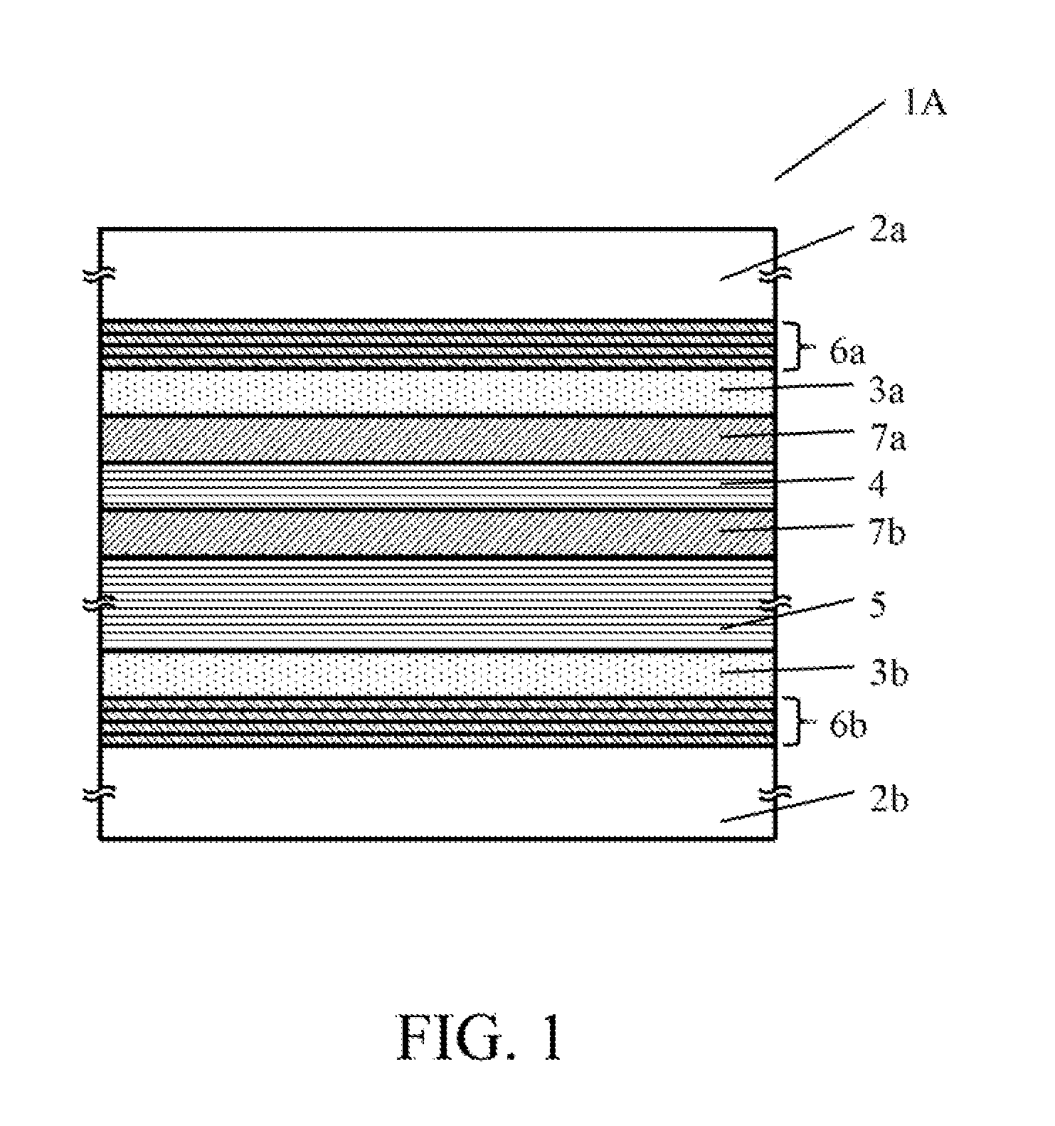
[0023]FIG. 1 is a sectional view of a variable transmittance element 1A according to a first embodiment. The variable transmittance element 1A includes substrates 2a and 2b, transparent electrode layers 3a and 3b, an electrochromic layer (EC layer) 4, an electrolyte layer 5, antireflective (“AR”) layers 6a, 6b, 7a, and 7b. In the variable transmittance element 1A, the substrate 2a, the AR layer 6a, the transparent electrode layer 3a, the AR layer 7a, the EC layer 4, the AR layer 7b, the electrolyte layer 5, the transparent electrode layer 3b, the AR layer 6b, and the substrate 2b are arranged in this order from the top.

[0024]The substrates 2a and 2b are flat plates or lenses. The two transparent electrode layers 3a and 3b are placed between these two substrates 2a and 2b, and made of ITO. The EC layer 4 has transmittance that is reversibly changed by electric control, is placed between the transparent electrode layers 3a and 3b, and is made of a high-density titanium oxide (TiO2). T...

second embodiment

[0053]FIG. 3 is a sectional view of a variable transmittance element 1B according to a second embodiment. The second embodiment is different from the first embodiment in that each of the transparent electrode layers 3a and 3b is as thin as 20 nm, there is no AR film 7a between the transparent electrode layer 3a and the EC layer 4 and the AR layer 7 of a single layer made of TiO2 is provided between the EC layer 4 and the electrolyte layer 5. Moreover, each of the AR layers 6a and 6b is a multilayer film in which four TiO2 layers and three SiO2 layers are alternately laminated in the second embodiment, and thus the number of layers of this embodiment is smaller than that of the first embodiment.

[0054]Table 3 shows a material, a refractive index n, an extinction coefficient k, and a film thickness of each layer in the second embodiment. The refractive index of each material means a refractive index for a wavelength of 550 nm.

TABLE 3FilmThick-ness dn(550 nm)k(550 nm)(nm)Substrate 2aGla...

third embodiment

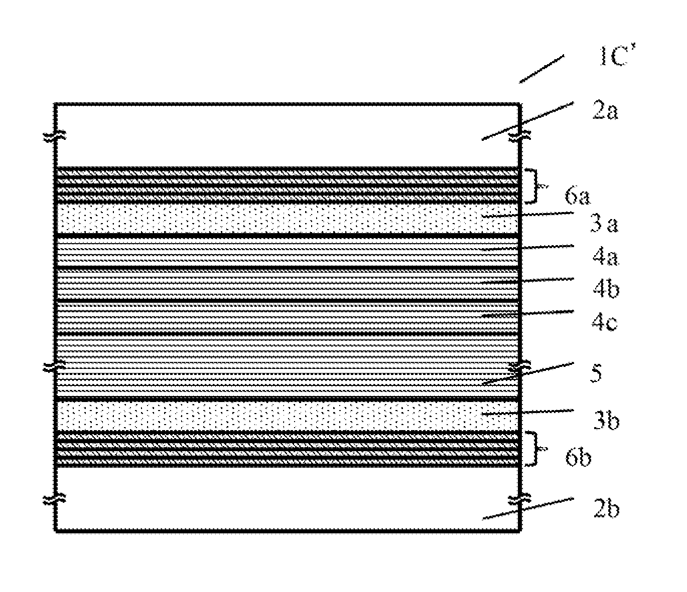
[0060]FIG. 5 is a sectional view of a variable transmittance element 1C according to a third embodiment. The third embodiment uses an organic EC layer that is different from the EC layers in the first and second embodiment, and the variable transmittance element 1C includes none of the AR layers 7, 7a and 7b as single layers of the first and second embodiments. Each of the AR layers 6a and 6b of the third embodiment is a multilayer film in which four TiO2 layers and four SiO2 layers are alternately laminated.

[0061]Table 5 shows a material, a refractive index n, an extinction coefficient k, and a film thickness of each layer in the variable transmittance element 1C. The refractive index of each material means a refractive index for a wavelength of 550 nm.

TABLE 5FilmThick-ness dn(550 nm)k(550 nm)(nm)Substrate 2aGlass1.520AntireflectiveSiO21.480218layer 6aTiO22.29010SiO21.48042TiO22.29014TransparentITO1.920.023100electrodelayer 3aEC layer 4Organic1.590500EC layerElectrolyte1.48050000(N...


PUM

PropertyMeasurementUnit
refractive indexaaaaaaaaaa

Abstract

A variable transmittance element includes two substrates, two transparent electrode layers held between the two substrates, an electrochromic layer held between the two transparent electrode layers and having transmittance that is reversibly changed by electric control, and a first dielectric layer provided between one of the two substrates and one of the two transparent electrode layers closest to the one of the two substrates and configured to reduce reflections. The first dielectric layer is a multilayer film made by alternately laminating two or more layers each having a high refractive index and two or more layers each having a low refractive index, a refractive index difference for a wavelength of 550 nm between the layer having the high refractive index and the layer having the low refractive index being 0.2 or more.

Description

BACKGROUND OF THE INVENTION[0001]1. Field of the Invention[0002]The present invention relates to a variable transmittance element, optical system, and optical apparatus utilizing an electrochromic material.[0003]2. Description of the Related Art[0004]Japanese Patent Laid-Open No. (“JP”) 6-95165 discloses a structure of a variable transmittance element in which an electrochromic (“EC”) layer and an electrolyte layer are laminated between a pair of transparent electrode layers held between a pair of substrates. The variable transmittance element utilizes an EC material which is colored by electric control and has a reversibly changing transmittance. JP 9-152634 proposes to provide an antireflective film on the side of the substrate opposite to the transparent electrode so as to improve the transmittance of the variable transmittance element that uses the EC material.[0005]When each of these variable transmittance elements is used for the image-pickup optical system and the light quant...

Claims


Application Information

Patent Timeline
Patent Type & Authority Applications(United States)
IPC IPC(8): G02F1/153G02F1/1524
CPCG02F1/1523G02F1/157G02F1/1524
Inventor USHIGOME, REONA
Owner CANON KK
Why Eureka
Try Eureka