
Lighting apparatus and image display apparatus provided therewith

a technology of image display apparatus and light source, which is applied in the field of light source apparatus, can solve the problems of shortening the life of the device in the image display apparatus, affecting the performance of the light source, and affecting the brightness of the image, so as to achieve the effect of reducing the uneven luminance, reducing the life of the device, and maintaining structural strength

Inactive Publication Date: 2013-04-18
SHARP KK
View PDF1 Cites 17 Cited by
  • Summary
  • Abstract
  • Description
  • Claims
  • Application Information

AI Technical Summary

Benefits of technology

The present invention is a lighting apparatus that includes a light source, a light guide member, a heat-releasing member, and a heat-conducting member. The heat-conducting member includes a light-source supporter and a plate section that contacts the heat-releasing member. The light source is positioned on the light-source supporter and the plate section faces the light-guide member. This design improves heat-releasing performance without compromising structural strength and reduces uneven lighting due to temperature variations. The heat-releasing member is connected to the light source supporting member, and the heat-conducting member contacts both the light-source supporting member and the heat-releasing member. The heat-conducting member includes two plate sections that align in a straight line with fixing sections in between. This simplifies production and reduces fixing areas. Overall, this lighting apparatus improves heat-releasing performance and reduces production costs.

Problems solved by technology

When this heat increases the temperature of the LED, emission efficiency drops and the lives of devices in an image display apparatus are shortened, which may result, in the worst case, in breakage of the devices and loss of emission.
This structure is disadvantageous in terms of heat release, because heat is easiest to be conducted and released when it is distributed evenly, and heat is more difficult to be conducted and released when it is distributed more uneven.
Consequently, light intensity required for one LED is larger, resulting in greater release of heat.
This situation is a problem common among light sources when they are used not as a direct type but as an edge-light type while enlarging the screen size.
In particular, LCD televisions and displays for personal computers are generally used in a landscape form, and accordingly suffer greater heat when light is introduced from horizontal two sides thereof than when light is introduced from vertical two sides thereof.
This causes a situation which conventional heat-releasing methods cannot deal with.

Method used


Image

  • Lighting apparatus and image display apparatus provided therewith
  • Lighting apparatus and image display apparatus provided therewith
  • Lighting apparatus and image display apparatus provided therewith

Examples


first embodiment

(I) Configuration of Lighting Apparatus in Accordance with the Present Embodiment

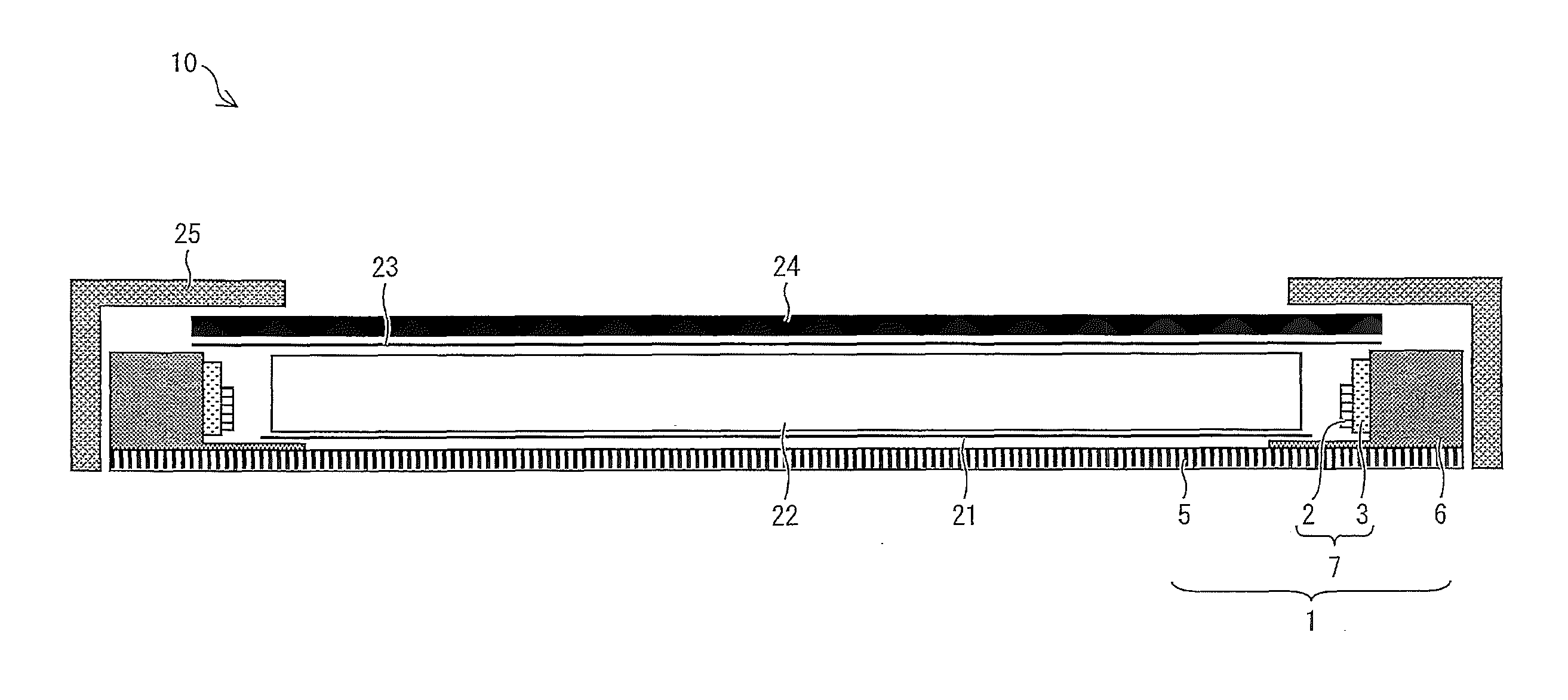
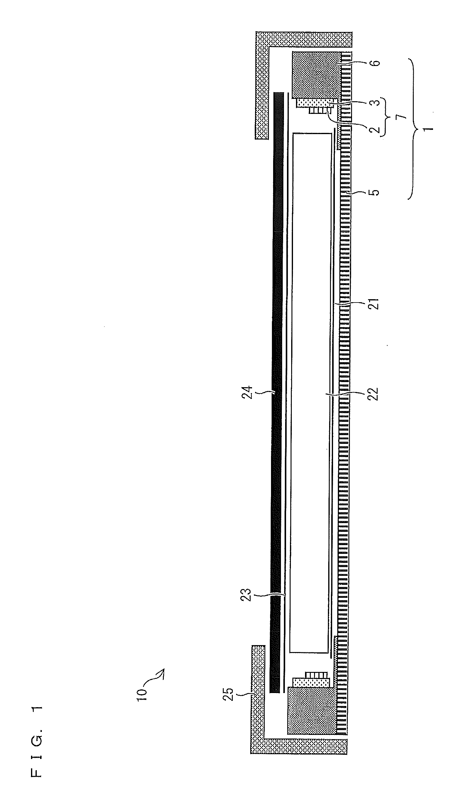
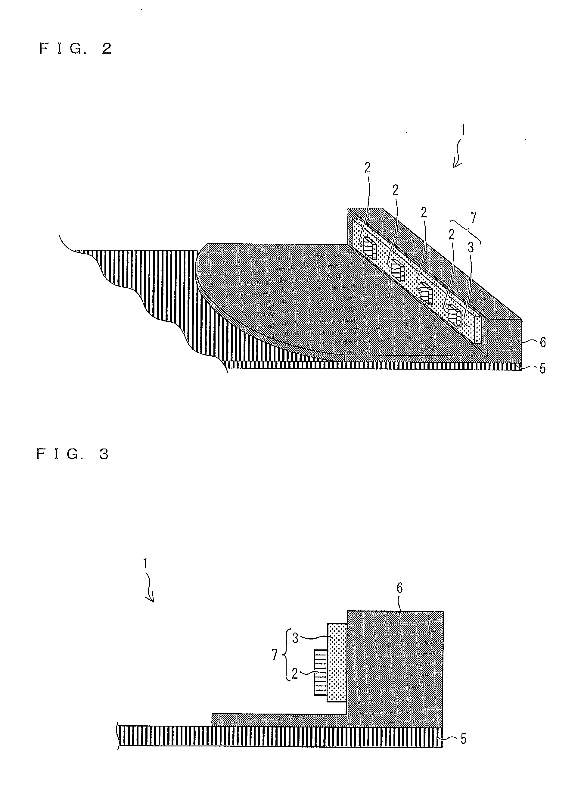
[0062]A lighting apparatus in accordance with the present embodiment includes: a light source; a light guide member having a light-incident plane and a light-emitting plane perpendicular to the light-incident plane; a heat-releasing member positioned at a backside of the light guide member so as to face the light-emitting plane; and a heat-conducting member for conducting heat from the light source to the heat-releasing member, the heat-conducting member including: a light-source supporter having a plane facing the light-incident plane; and a plate section having a plane facing the light-emitting plane and a plane facing the heat-releasing member, the light-source supporter being adjacent to the plate section, on the light-source supporter, the light source being positioned on the plane facing the light-incident plane in such a manner as to face the light-incident plane, the plane of the plate section w...

second embodiment

[0109]The following explains the present embodiment with reference to FIGS. 10 and 11. For convenience of explanation, members having the same functions as those explained in First Embodiment with reference to the drawings are given the same reference signs and explanations thereof are omitted. Furthermore, terms already explained in First Embodiment are not explained here.

(I) Configuration of Lighting Apparatus in Accordance with the Present Embodiment

[0110]A lighting apparatus in accordance with the present embodiment is different from the lighting apparatus in accordance with First Embodiment in that the heat spreader 6 is not “constituted by integrally forming the frame 17 and the heat-conducting plate 16” but “constituted by separately forming the frame 17 and the heat-conducting plate 16”.

[0111]Specifically, FIG. 10 is a cross sectional view schematically showing a configuration of a liquid crystal display device (image display apparatus) 10 including a backlight apparatus (li...

third embodiment

[0124]The following explains the present embodiment with reference to FIGS. 12 to 15. For convenience of explanation, members having the same functions as those explained in First Embodiment with reference to the drawings are given the same reference signs and explanations thereof are omitted. Furthermore, terms already explained in First Embodiment are not explained here.

(I) Configuration of Lighting Apparatus in Accordance with the Present Embodiment

[0125]Compared with the lighting apparatus in accordance with First Embodiment, a lighting apparatus in accordance with the present embodiment further includes a reinforcing member for reinforcing a heat spreader 6.

[0126]Specifically, FIG. 12 is a cross sectional view schematically showing a configuration of a liquid crystal display device (image display apparatus) 10 including a backlight apparatus (lighting apparatus) 1 in accordance with the present embodiment. FIG. 13 shows the shape of the heat spreader 6 in accordance with the pr...


PUM


Abstract

Provided are a lighting apparatus capable of improving heat-releasing performance while maintaining structural strength, subduing luminance unevenness due to uneven heat distribution, and allowing the device to be thinner, and an image display apparatus including the lighting apparatus. A heat-conducting member (6) includes: a light-source supporter having a plane facing a light-incident plane; and a plate section having a plane facing a light-emitting plane and a plane facing a heat-releasing member (5), the light-source supporter being adjacent to the plate section. On the light-source supporter, a light source (7) is positioned on the plane facing the light-incident plane so as to face the light-incident plane, the plane of the plate section which faces the heat-releasing member (5) contacts a plane of the heat-releasing member (5) which faces a light guide member, and a centroid of the plate section deviates along a direction parallel to both the light-incident and light-emitting planes.

Description

TECHNICAL FIELD[0001]The present invention relates to a lighting apparatus used in an image display apparatus such as a liquid crystal display device.BACKGROUND ART[0002]In general, an image display apparatus such as a liquid crystal display device consists of a display panel for controlling brightness, color etc. of pixels, a backlight apparatus (lighting apparatus) for emitting light to the display panel, and a control circuit for controlling them and a circuit substrate.[0003]The backlight apparatus diffuses light in the image display apparatus so as to emit light to the display panel in a planar manner. The backlight apparatus includes a direct type designed such that light sources are provided at the backside of the backlight apparatus in a distributed manner and an edge-light type (also referred to as “side-light type) designed such that light sources are provided at the side of the backlight apparatus so as to illuminate therefrom. The edge-light type backlight apparatus has ...

Claims


Application Information

Patent Timeline
IPC IPC(8): F21V29/00
CPCG02B6/0085F21V29/20G02F2001/133628G02F1/133615G02F1/133628
Inventor KANDA, HIROFUMISUMIKAWA, MASATOTAKAYAMA, TAKESHISAKAI, KOYUMORI, KEIKO
Owner SHARP KK
Learn More