Monitoring Structural Shape or Deformations with Helical-Core Optical Fiber

a technology of optical fiber and helical core, which is applied in the field of oil exploration and production, can solve the problems of sensor inability to give measurements relating to bending direction and torque, and other parameters

Inactive Publication Date: 2013-04-18
BAKER HUGHES INC
View PDF15 Cites 27 Cited by
  • Summary
  • Abstract
  • Description
  • Claims
  • Application Information

AI Technical Summary

Problems solved by technology

Such sensors are unable to give measurements relating to bending direction and torque, as well as other parameters.

Method used


Image

  • Monitoring Structural Shape or Deformations with Helical-Core Optical Fiber
  • Monitoring Structural Shape or Deformations with Helical-Core Optical Fiber
  • Monitoring Structural Shape or Deformations with Helical-Core Optical Fiber

Examples


Embodiment Construction

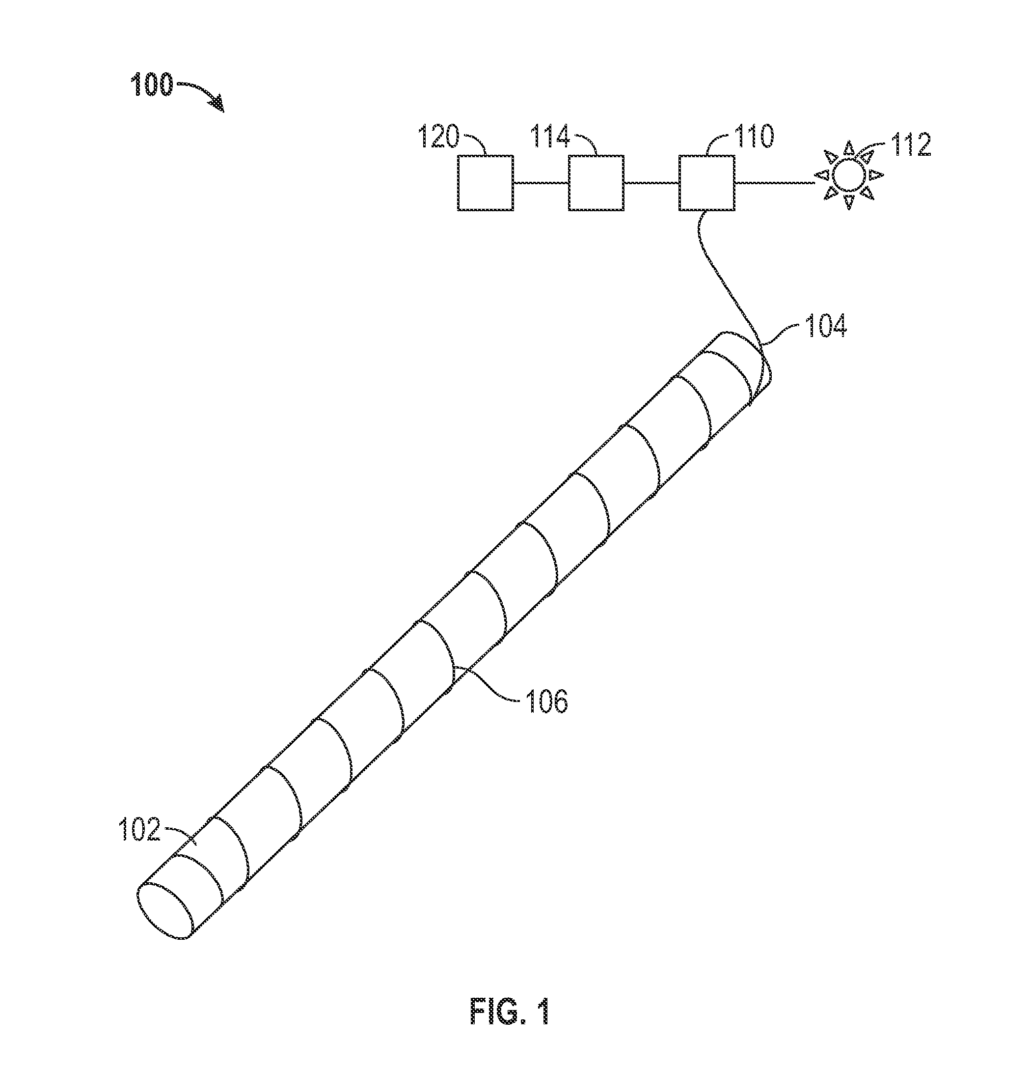
[0013]FIG. 1 shows an exemplary fiber optic cable 104 of the present disclosure coupled to a member 102 to obtain signals related to a parameter of the member. The member 102 can be used in various aspects of oil production or exploration as a member of a measurement-while-drilling tool, a borehole casing, a wireline logging device, a sandscreen, or a fiber express tube, for example. Signals obtained via the fiber optic cable 104 can be used, for example, to determine a local strain at the member as well as temperature measurements, member deformation and other parameters. These measurements can be used in various embodiments for Real Time Compaction Monitoring (RTCM), Distributed Temperature Sensing (DTS), Optical Frequency Domain Reflectometry (OFDR), and various methods using swept-wavelength interferometry.

[0014]The fiber optic cable 104 is typically wrapped around the member 102 at a determined wrapping angle and includes a plurality of sensors 106 therein. The sensors 106 in o...


PUM


Abstract

A method, apparatus and system for determine a parameter of a structure is disclosed. A fiber optic cable is coupled to a member. The fiber optic cable includes at least a first core helically arranged in the fiber optic cable that includes at least a first sensor and a second sensor. A first measurement related to the parameter is obtained at the first sensor, and a second measurement at the second sensor related to the parameter is obtained at the second sensor. A difference between the first and second measurements is used to determine the parameter.

Description

CROSS-REFERENCE TO RELATED APPLICATIONS[0001]This application claims priority to U.S. Provisional Application Ser. No. 61 / 546,319,filed Oct. 12, 2011.BACKGROUND OF THE DISCLOSURE[0002]In various aspects of oil exploration and production, a fiber optic cable having a plurality of optical sensors formed therein is employed to obtain information from downhole locations. The fiber optic cable typically extends from a surface location and is coupled to a member at the downhole location. A light source deployed at the surface propagates light through the fiber optic cable. The propagating light interacts with at least one of the plurality of optical sensors to produce a signal indicative of a parameter of the downhole member. The signal is then detected at the surface location. Typically, fiber optic cables include a single core along a central axis of the fiber optic cable. Such sensors are unable to give measurements relating to bending direction and torque, as well as other parameters....

Claims


Application Information

Patent Timeline
Patent Type & Authority Applications(United States)
IPC IPC(8): G01B11/16G02B6/34
CPCE21B47/0006G01L1/246G01B11/18E21B47/123E21B47/007E21B47/135E21B47/00G01B11/16G01L1/24
Inventor DUNCAN, ROGER G.CHILDERS, BROOKS A.HALL, TRAVIS S.
Owner BAKER HUGHES INC
Why Eureka
Try Eureka