Fiber-optic cable with fitting

a fiber-optic cable and fitting technology, applied in the direction of optics, fibre mechanical structures, instruments, etc., can solve the problems of configuration not being able to obtain sufficient increasing the number of components and processes, etc., to increase the fixing strength of the sheath, reduce movement, and increase connection strength

Active Publication Date: 2013-04-18
AUTONETWORKS TECH LTD +2
View PDF2 Cites 8 Cited by
  • Summary
  • Abstract
  • Description
  • Claims
  • Application Information

AI Technical Summary

Benefits of technology

[0012]The fiber-optic cable with the fitting of the present invention can increase connection strength between the fitting and the fiber-optic cable, especially can increase fixing strength of the sheath.
[0013]In a conventional configuration shown in FIG. 11A such that a fitting 82 is mounted on a sheath 811 of a fiber-optic cable 81 at a position very close to an end face of the sheath 811, the sheath 811 does not have a portion that is not compressed or deformed on a front-end side more front than a first portion 821 of the fitting 82 (alternatively, the sheath 811 itself does not exist there). Thus, the fitting 82 and the sheath 811 are connected with each other only by the friction between the fitting 82 and the compressed circumference of the sheath 811. In this case, if a pull force larger than the friction is exerted between the sheath 811 and the fitting 82, the sheath 811 moves in an axial direction inside the fitting 82 to fall off the fitting 82 as shown in FIG. 11B because a tensile member 812 and the sheath 811 do not have a monolithic construction.
[0014]In contrast, in the fiber-optic cable with the fitting of the preferred embodiment of the present invention, the sheath has a portion that is not compressed or deformed on a front-end side more front than the first portion of the fitting. Thus, if a pull force larger than the friction is exerted between the sheath and the fitting, the portion that is not compressed or deformed is caught by the fitting to prevent the sheath from moving, or to minimize the movement. That is, in order to move the sheath in the axial direction, it is necessary to not only exert a force larger than the friction between the first portion of the fitting and the sheath, but also compress and deform the end portion of the sheath. For this reason, the connection strength between the fitting and the sheath increases compared with the configuration that the fitting and the sheath are connected with each other only by friction (in other words, the force necessary to move the sheath in the axial direction becomes larger).
[0015]In addition, the tensile member is drawn out of the sheath through the slit at a portion of the sheath on the front-end side more front than the first portion of the fitting. The tensile member is fitted (i.e., lies) in the slit at this portion of the sheath, so that the slit is pushed to stretch out in a circumferential direction to make this portion of the sheath larger in size in the circumferential direction than the other portion of the sheath. Thus, this portion of the sheath can prevent the sheath from falling off the fitting or minimize the fall more efficiently than the other portion of the sheath. In other words, though the fitting needs to pass through this portion of the sheath in order to move toward the end portion of the sheath, a force necessary to compress and deform this portion of the sheath is larger than a force necessary to compress and deform the other portion because this portion of the sheath is larger in external diameter than the other portion. For this reason, the connection strength between the fitting and the sheath increases.
[0016]Further, in the fiber-optic cable with the fitting of the present invention, the length in the axial direction of the first portion of the fitting can be made short, and the connection strength between the fitting and the fiber-optic cable can be increased at the same time. Alternatively, even if the length in the axial direction of the first portion of the fitting is made short, reduction in the connection strength between the fitting and the fiber-optic cable can be prevented or minimized. Thus, the fitting can be reduced in size. Then, the reduction in size of the fitting can reduce the size of an entire optical connector.

Problems solved by technology

However, because the optical cable connector of PTL 1 has the configuration that the tensile member and the sheath are sandwiched by the different members, there arises a problem that the numbers of components and processes increase.
However, because a crimping base is not used, the configuration could not obtain sufficient fixing strength of the sheath.

Method used


Image

  • Fiber-optic cable with fitting
  • Fiber-optic cable with fitting
  • Fiber-optic cable with fitting

Examples


Embodiment Construction

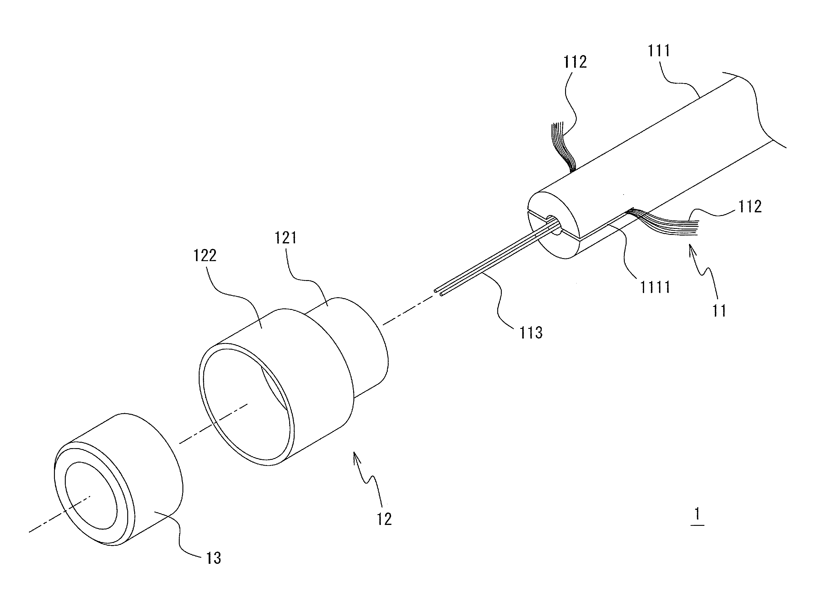
[0028]Detailed descriptions of preferred embodiments of the present invention will now be provided with reference to the accompanying drawings. It is to be noted that hereinafter “an axial direction” of each component of a fiber-optic cable with a fitting of the preferred embodiments of the present invention defines the longitudinal direction of a fiber-optic cable where the built-up fiber-optic cable with the fitting of the preferred embodiments of the present invention is used as a standard. Likewise, “a front-end side” defines the side closer to an end portion of the fiber-optic cable (i.e., the end portion where a fitting is mounted), and “a rear-end side” defines the side farther to the end portion of the fiber-optic cable.

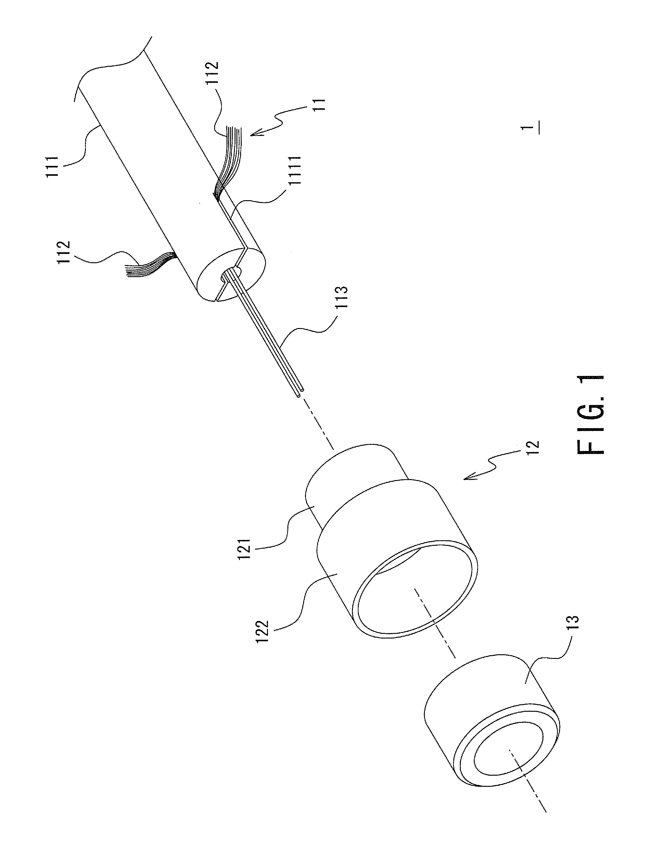
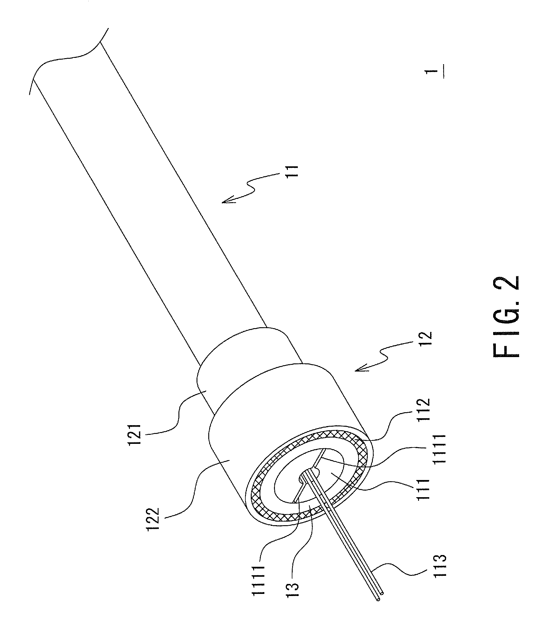
[0029]FIG. 1 is an exploded perspective view showing a configuration of a fiber-optic cable 1 with a fitting of one preferred embodiment of the present invention. FIG. 2 is an external perspective view showing the configuration of the fiber-optic cable 1 with...


PUM


Abstract

A fiber-optic cable with a fitting capable of increasing connection strength between a fiber-optic cable and an optical connector, which includes a fiber-optic cable including a sheath and a tensile member, an inner ring mounted on a circumference of the sheath from a position where the tensile member is drawn out of the sheath through a slit to a front end of the sheath, and a fitting mounted on the circumference and including a first portion mounted from the position where the tensile member is drawn out of the sheath to a position of the sheath on a side opposite to the ring side, and a second portion mounted while covering a circumference of the ring, wherein the first portion connects with the sheath, and the end portion of the tensile member is sandwiched by the ring and the second portion.

Description

TECHNICAL FIELD[0001]The present invention relates to a fiber-optic cable with a fitting, and more specifically relates to a fiber-optic cable with a fitting, which includes a fitting that is arranged to connect the fiber-optic cable and an optical connector by being fitted to the optical connector.BACKGROUND ART[0002]In automobiles, the volumes of in-car communication traffic have increased with an increase in in-car electrical components. Thus, in order to cope with the increased volumes of in-car communication traffic, measures to shift in-car communication media of electric wires to fiber-optic cables that include optical fibers and are capable of transmitting larger volumes of data at higher speed than the electric wires have been taken.[0003]Optical connectors are used for connecting the fiber-optic cables, or connecting the fiber-optic cable and an optical transmitter and receiver module mounted on a circuit board. In carrying out wiring of the fiber-optic cables in an automo...

Claims


Application Information

Patent Timeline
Patent Type & Authority Applications(United States)
IPC IPC(8): G02B6/44
CPCG02B6/443G02B6/3889G02B6/3888
Inventor ISHIDA, HIDETOSHIMAESOBA, HIROYOSHITANAKA, TETSUJI
Owner AUTONETWORKS TECH LTD
Why Eureka
Try Eureka