Distributed propulsion system and method of control

a technology of distributed propulsion and power system, which is applied in the direction of marine propulsion, rotors, vessel construction, etc., can solve the problems of high degree of control, electrical complexity of the system, prohibitively large and heavy,

Active Publication Date: 2013-04-18
ROLLS ROYCE PLC
View PDF11 Cites 121 Cited by
  • Summary
  • Abstract
  • Description
  • Claims
  • Application Information

AI Technical Summary

Benefits of technology

[0009]Using adjustable pitch to control the power distribution in an electrical distributed propulsive system allows the power taken or delivered by a propulsive unit to be controlled without an electronic power convertor. This provides significant benefits in terms of weight and reliability for an aircraft based system. The method can also be used advantageously used to actively damp oscillations in the propulsive system.

Problems solved by technology

However, such a system is electrically complex and would require a high degree of control to keep it stable.
However these would be prohibitively large and heavy for the required levels of power and redundancy required for aero applications.

Method used


Image

  • Distributed propulsion system and method of control
  • Distributed propulsion system and method of control
  • Distributed propulsion system and method of control

Examples


Embodiment Construction

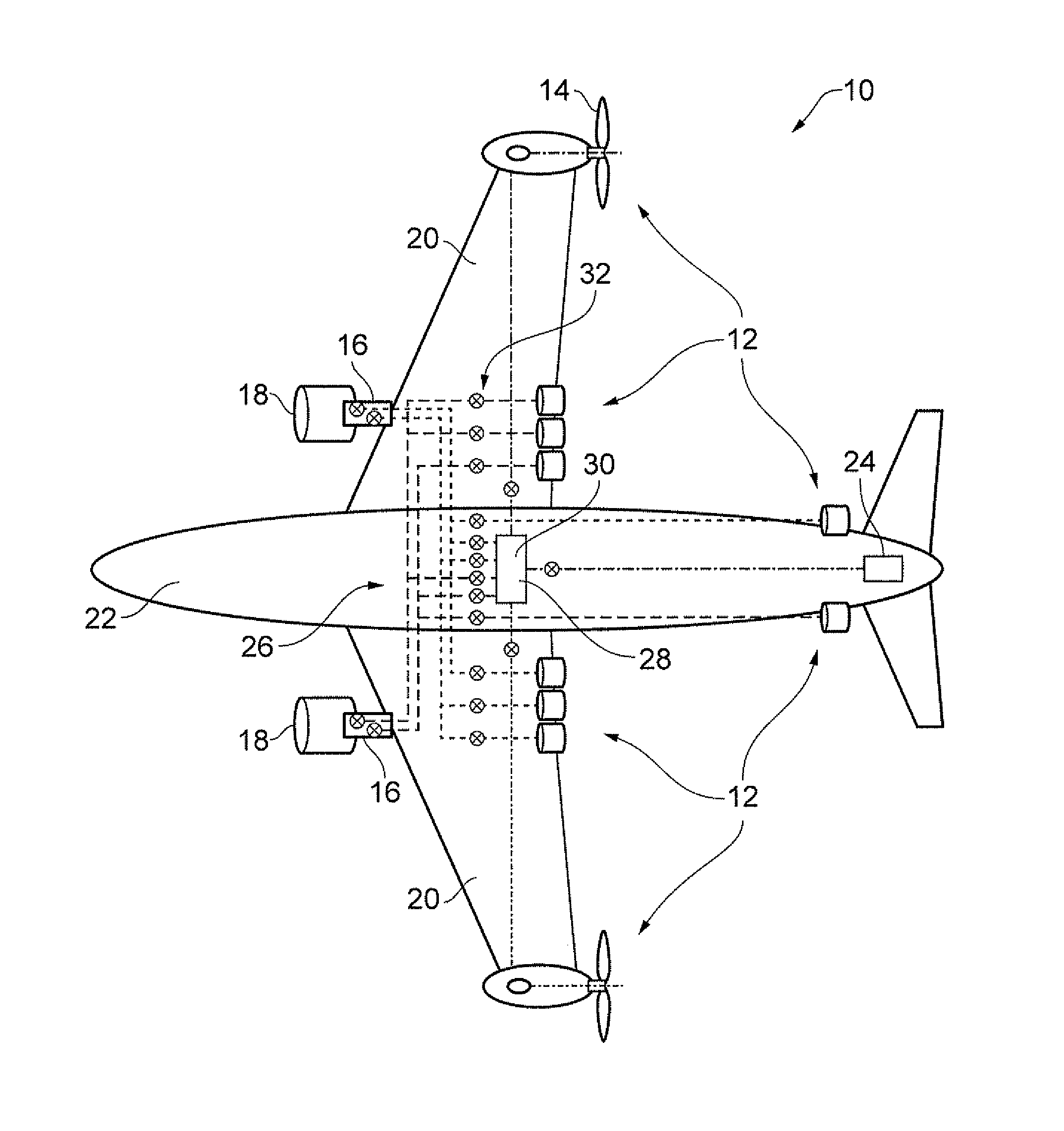
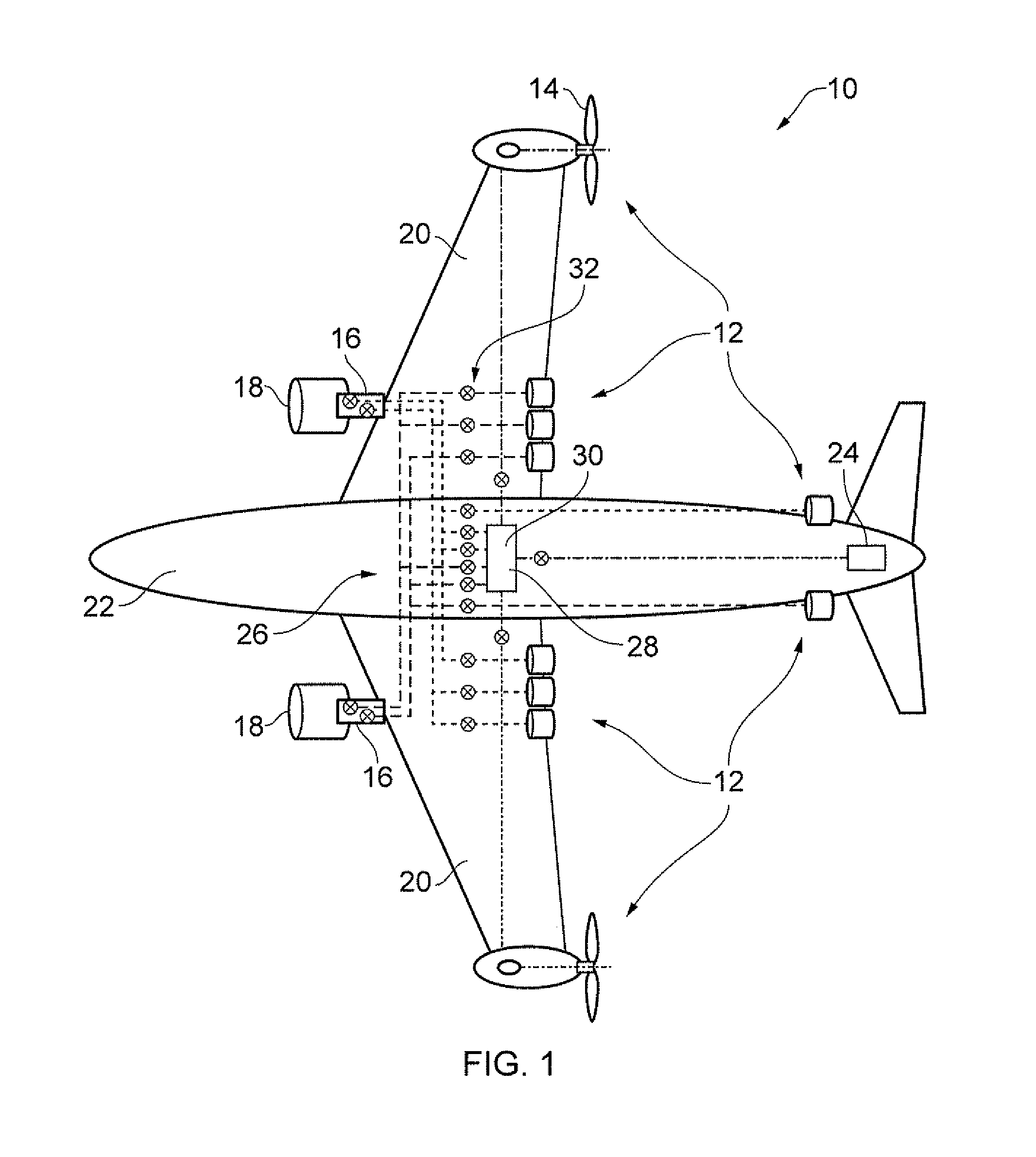
[0025]In FIG. 1 there is shown a schematic representation of an aircraft having the electrical propulsive system 10 according to the present invention. The electrical propulsive system 10 includes a plurality of electrical propulsion units in the form of fans 12 which are rotatably driven by superconducting electrical machines. Each of the fan units 12 includes a rotor having fan blades 14 mounted on a rotatable hub and a blade pitch adjustment mechanism for synchronously adjusting the pitch of the blades 14 relative to the air flow which passes them in use. Although only the propulsive units on the wings are shown as having blades 14, it will be appreciated that all of the propulsive units 12 include fans and blade arrangements as described.

[0026]The pitch adjustment mechanism can be any known in the art. In one embodiment, each fan blade 14 is mounted to the hub so as to be rotatable about its longitudinal axis via a shaft which passes into the hub and engages with the pitch contr...


PUM


Abstract

This invention relates to a method and apparatus for controlling power distribution in an electrical aircraft propulsive system having at least one electrical propulsion unit which includes a plurality of rotatable blades, each blade having an adjustable pitch; a pitch adjusting mechanism for adjusting the pitch of the blades; at least one electrical machine electrically connected to the electrical propulsion unit so as to provide electrical power when in use; and, a control system, the method comprising the steps of: determining the required propulsion; determining whether the propulsive units are delivering the required propulsion; and, adjusting the pitch angle of the blades of at least one propulsive unit so as to increase or decrease the propulsion provided by that propulsive unit.

Description

TECHNICAL FIELD OF INVENTION [0001]This invention relates to an electrical distributed power system for an aircraft and a method of controlling the same. In particular, this invention relates to the use of blade pitch control to distribute power and manage parasitic oscillations within the system.BACKGROUND OF INVENTION [0002]Conventional state of the art propulsion systems for large civil aircraft typically include one or more gas turbine engines placed under the wings of the aircraft. However, some studies have indicated that so-called distributed propulsion, which involves having numerous smaller propulsion units preferentially arranged around an aircraft, may provide some significant benefits in terms of noise reduction and fuel efficiency when compared with the current state of the art propulsive arrangements.[0003]One known arrangement for distributed propulsion is that used for helicopters where one or more engines is connected to two variable pitch rotors, either to two main...

Claims


Application Information

Patent Timeline
Patent Type & Authority Applications(United States)
IPC IPC(8): B64C11/30F01D7/00
CPCB64D27/02Y02T50/62B64D27/24Y02T50/60
Inventor ROLT, ANDREW MARTIN
Owner ROLLS ROYCE PLC
Why Eureka
Try Eureka