

Tool handling device for machine tools
a technology for handling devices and machine tools, applied in the direction of manufacturing tools, transportation and packaging, metal-working machine components, etc., can solve the problems of restricted maximum travel distance and extensive technology of known handling devices, and achieve the effect of sufficiently long travel distance, small required space and simple structur
- Summary
- Abstract
- Description
- Claims
- Application Information
AI Technical Summary
Benefits of technology
Problems solved by technology
Method used
Image

Examples
Embodiment Construction
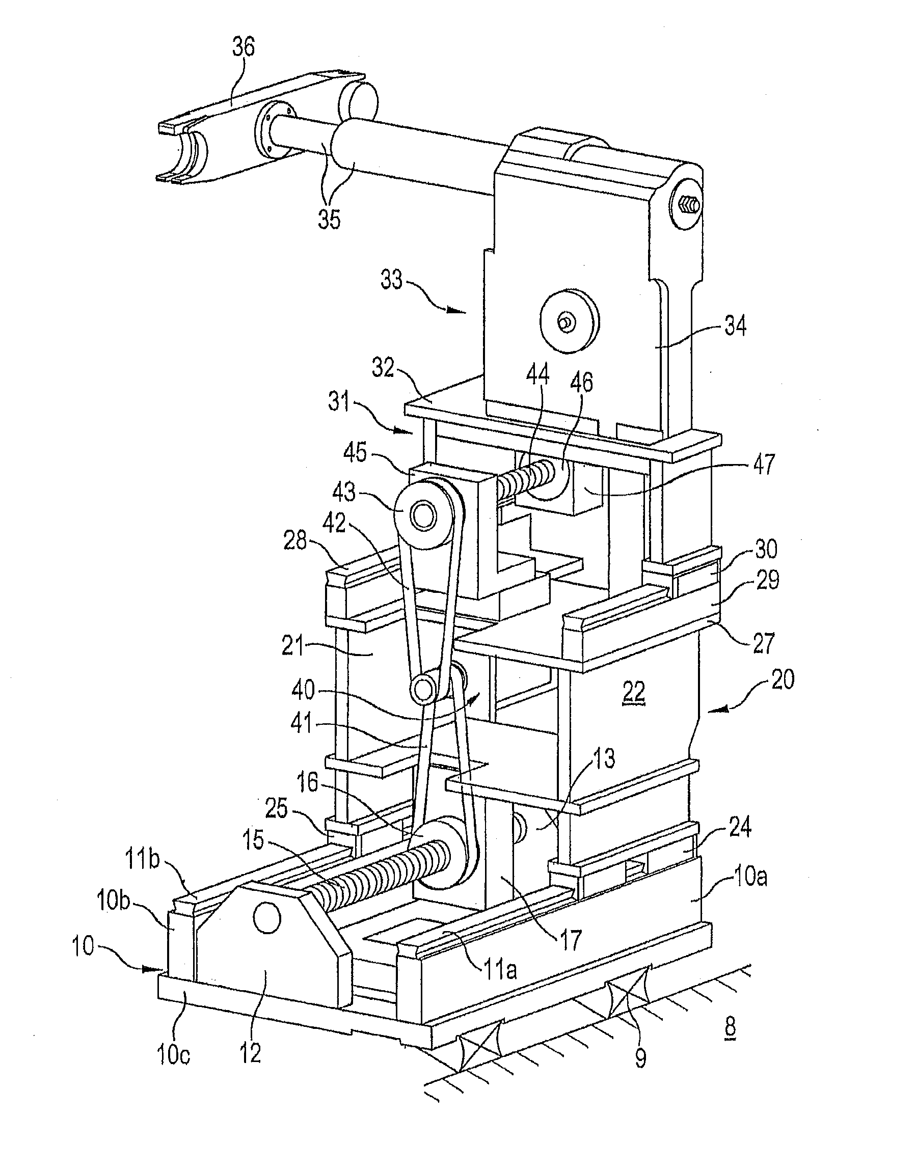
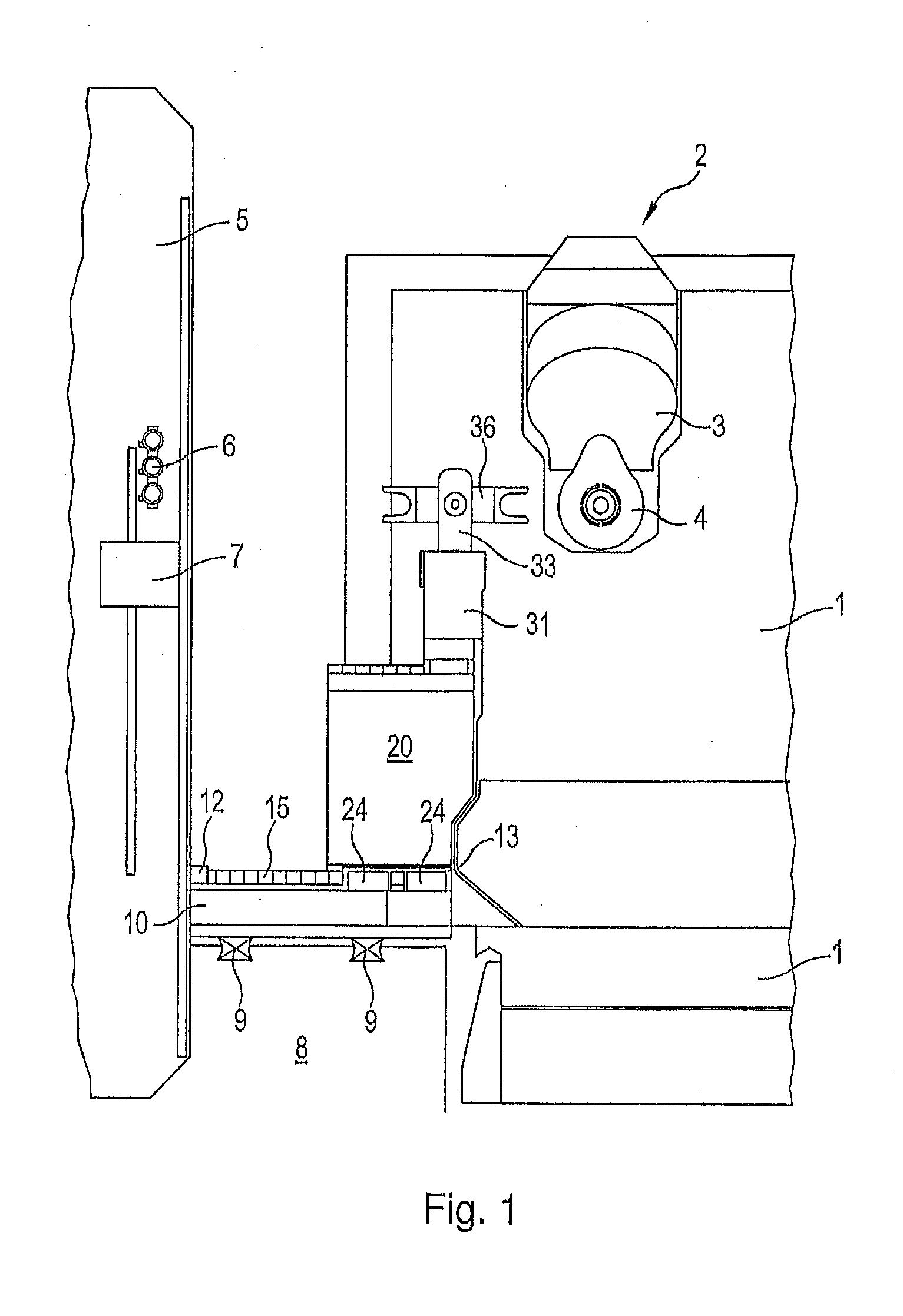
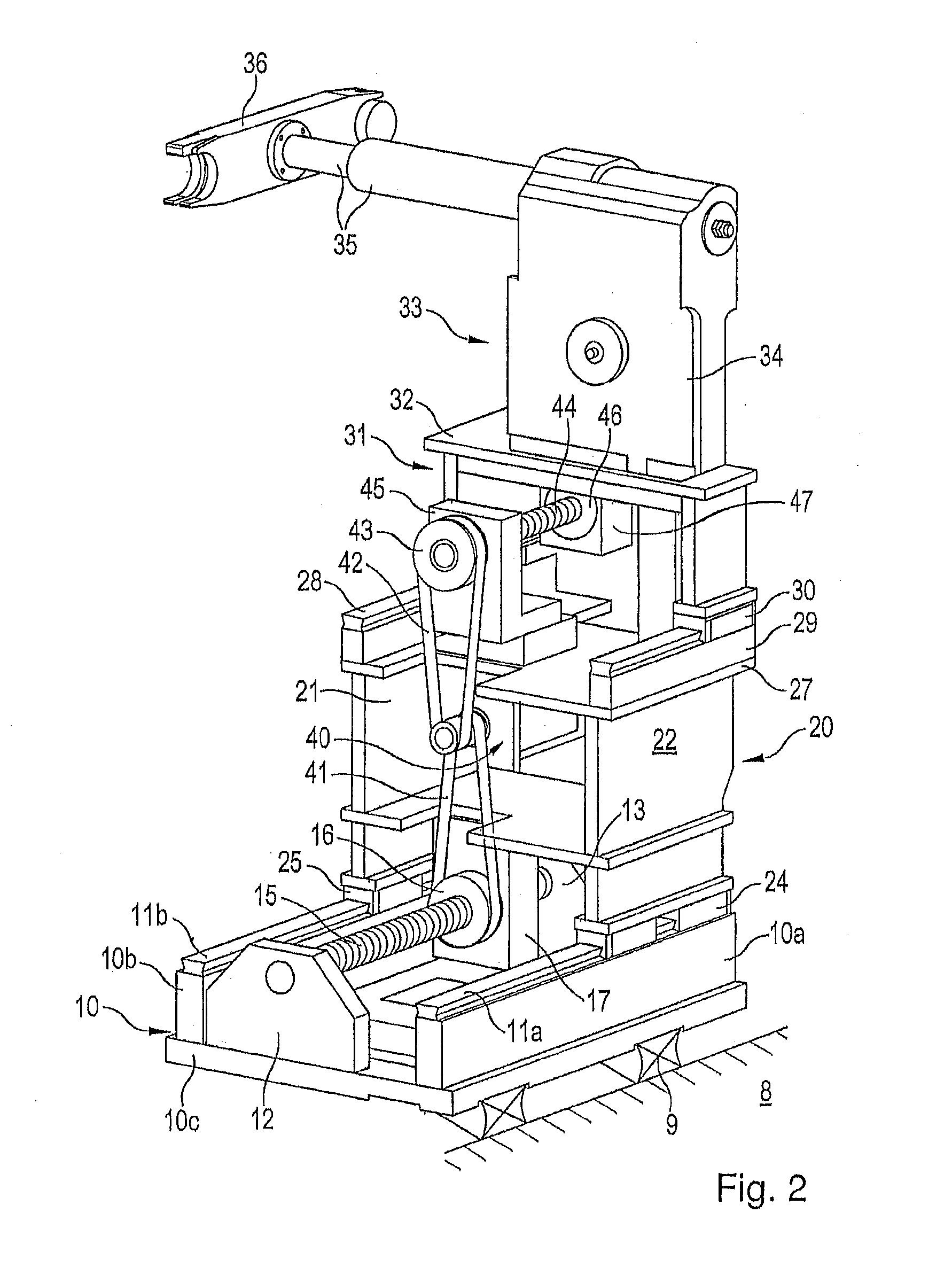
[0003]It is a purpose of the invention embodiments to provide a tool handling device for machine tools which is designed to be technically simple and which, in addition to little required space, enables sufficiently long travel distances for the tool changer.
[0004]This benefit is achieved by the facts that the supporting structure has two slides that are arranged on top of each other and can be displaced in the same direction, that a respective linear drive is mounted on each of the two slides, and that the two linear drives are driven by common motor, whereby a telescopic overall movement of the tool changer between the transfer position on the tool magazine and the exchange position on the work spindle is achieved.
[0005]A benefit of the concept is the fact that an additional handling apparatus used as a rule in the prior art, which takes the individual tools from the magazine and hands them over into a correspondingly positioned tool changer, is not necessary, so that the sequence...
PUM
 Abstract
Description
Claims
Application Information