Multistage heat exchanging duct comprising a parallel conduit

a heat exchanger and parallel conduit technology, applied in the field of heat exchangers, can solve the problems of increasing driving energy, increasing electrical current consumption, and reducing cooling efficiency, and achieve the effect of small required space and good performan

Inactive Publication Date: 2015-05-05
NFT NANOFILTERTECHN
View PDF26 Cites 5 Cited by
  • Summary
  • Abstract
  • Description
  • Claims
  • Application Information

AI Technical Summary

Benefits of technology

[0011]Therefore, it is an object of the invention to improve the heat exchanger of the above-mentioned type in such a way that it has a good performance and simultaneously a small required space even with greater surfaces to be cooled or to be heated.

Problems solved by technology

As shown in the above mentioned prior art, it is often necessary to cool or heat elongated surfaces, wherein the problem of the decreasing cooling efficiency with increasing length arises.
This, however, requires greater dimensioned feeding devices for the fluid, thus for example greater dimensioned blowers, which causes higher driving energy and therewith mostly a higher electrical current consumption as well as an increased required space and finally also a higher noise emission.

Method used


Image

  • Multistage heat exchanging duct comprising a parallel conduit
  • Multistage heat exchanging duct comprising a parallel conduit
  • Multistage heat exchanging duct comprising a parallel conduit

Examples


Embodiment Construction

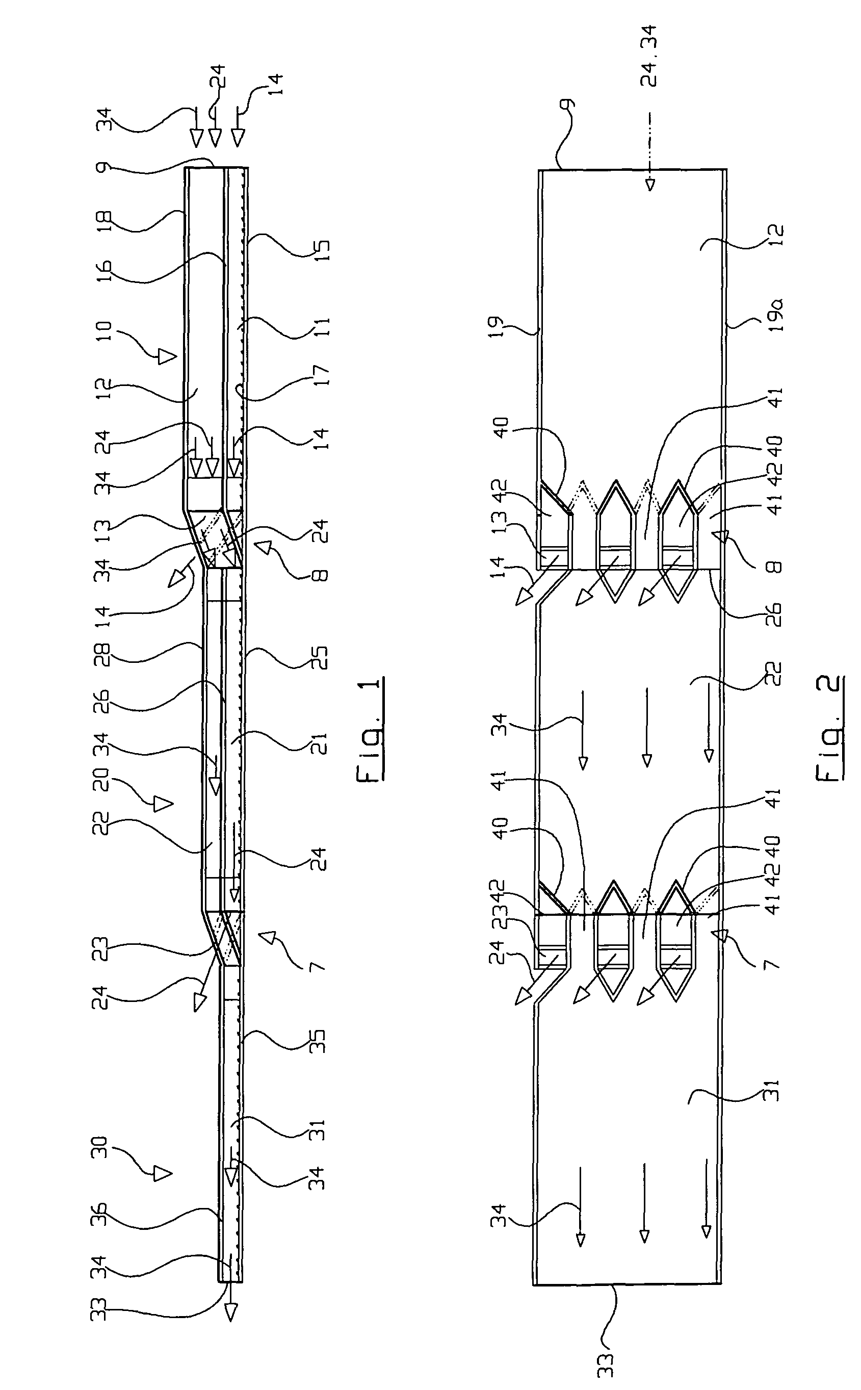
[0029]FIG. 1 shows a schematic side view of the heat exchanger, which here has three stages 10, 20 and 30. The first stage 10 has a heat exchanging channel 11, wherethrough a fluid, like for example air, may flow, namely with a first part flow 14, which is denoted by an arrow. The heat exchanging channel 11 has a heat transfer wall 15, which is in a heat transferring interaction with the part flow 14, wherein this wall 15 may comprise elements on its inner side, which improve a heat transfer, as for example cooling ribs, roughnesses or micro ribs according to DE 102 33 736 B3.

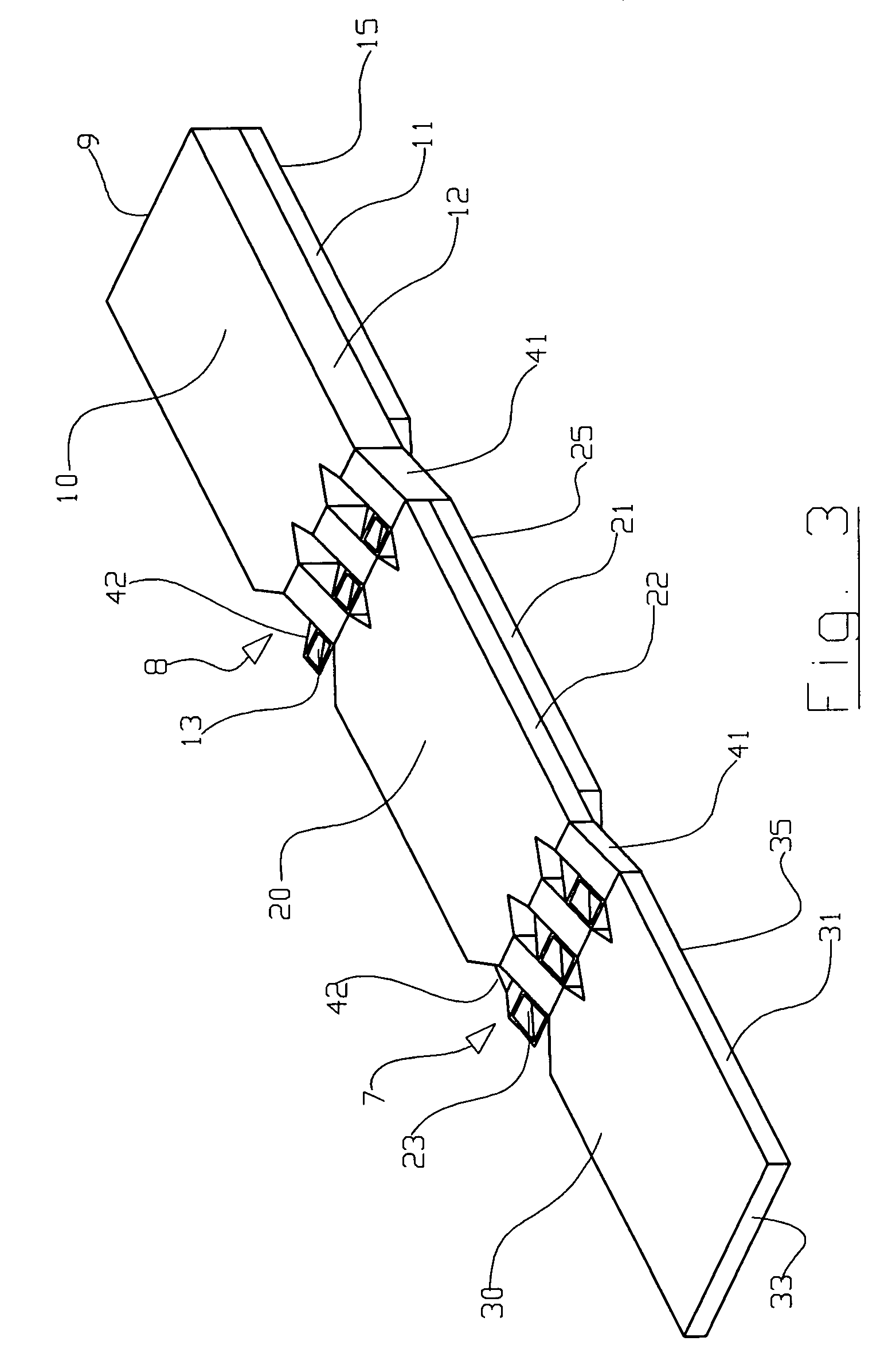
[0030]The heat exchange channel 11 further has a dividing wall 16, which separates the heat exchanging channel 11 from a guiding channel 12 lying thereabove. The guiding channel 12 is closed by a topwall 18. Both channels 11 and 12 are closed at their sides by common side walls 19 and 19a (compare FIG. 2). Both channels have a common inlet 9 for a fluid, which is separated by the dividing wall 16 into part flow...


PUM


Abstract

The heat exchanger having a heat exchanging channel (11, 21, 31) comprises an inlet (9) and an outlet (33) for a medium flowing through the heat exchanging channel. The heat exchanger has at least two stages (10, 20, 30) being arranged one after the other in view to the flowing direction of the medium, each stage having a heat exchanging channel (11, 21, 31). The first stage has at least one guiding channel (12) arranged parallel to the heat exchanging channel (11). The heat exchanging channel (11, 21, 31) has at the end of the respective stage (10, 20, 30) at least one outlet (13, 23, 33) and the guiding channel (12, 22) of the respective stage is connected with the heat exchanging channel (21, 31) of the next following stage (20, 30). By this unused heat transfer medium is fed to each stage, said heat transfer medium having a higher temperature difference with respect to the respective heat exchanging channel. By this a good heat transfer efficiency is realized even with relatively long flow pathes.

Description

CROSS-REFERENCE TO RELATED APPLICATIONS[0001]This application claims priority from German application 10 2006 018 709.1, filed Apr. 20, 2006, now Patent DE 10 2006 018 709; and from German application DE 10 2006 035 552.0 filed Jul. 27, 2006, the entire disclosures of which are incorporated by reference.FIELD OF THE INVENTION[0002]The invention relates to a heat exchanger of the type having an inlet and an outlet and a channel through which a heat-exchanging medium flows.BACKGROUND OF THE INVENTION[0003]Such a heat exchanger is for example known from DE 10 2004 030 675 A1. For cooling of electronic components, which are arranged within a switch cabinet, there is formed a channel together with a wall of the switch cabinet, and a medium such as air flows through the channel. The channel has an inlet for cool air and an outlet for heated air. Cooling elements are arranged on a channel wall, which shall provide for a better heat transfer from that wall to the air flowing along it.[0004]...

Claims


Application Information

Patent Timeline
Patent Type & Authority Patents(United States)
IPC IPC(8): H05K7/20F28D1/06F28D21/00F28F3/12F28F9/22H01L23/467
CPCH01L23/467F28D1/06F28F3/12H05K7/206F28D2021/0031F28F2009/228H01L2924/0002H01L2924/00
Inventor HOFMANN, WILFRIED
Owner NFT NANOFILTERTECHN
Why Eureka
Try Eureka