Heat transfer compositions of hydrofluorocarbons and a hydrofluoroolefin

a technology of hydrofluorocarbons and compositions, which is applied in the field of heat transfer compositions, can solve the problems of compromising performance characteristics, affecting the performance of hfcs, and affecting the quality of hfcs, and can be considerably more expensive for new lubricants

Inactive Publication Date: 2013-04-18
ARKEMA INC
View PDF16 Cites 147 Cited by
  • Summary
  • Abstract
  • Description
  • Claims
  • Application Information

AI Technical Summary

Problems solved by technology

However, most of the HFC-based R-22 replacements have higher global warming potential (GWP) than R-22 while also compromising in performance characteristics.
Another limitation is that most HFCs lack the miscibility with traditional lubricants, such as mineral oils, necessary to provide adequate performance.
These new lubricants can be considerably more expensive than traditional mineral oil lubricants and can be extremely hygroscopic.

Method used


Image

  • Heat transfer compositions of hydrofluorocarbons and a hydrofluoroolefin
  • Heat transfer compositions of hydrofluorocarbons and a hydrofluoroolefin

Examples


example 1

[0091]To a high-pressure cylinder was added a composition containing 21 wt % R-32 (difluoromethane), 25 wt % R-125 (pentafluoroethane), 22 wt % R-1234yf (2,3,3,3-tetrafluoropropene), and 32 wt % R-134a (1,1,1,2-tetrafluoroethane). Afterwards, the liquid and vapor fractions of the cylinder contents were analyzed by gas chromatography to determine the composition. The compositions are shown in Table 6; each of the compositions are either non-flammable or have very low flammability characteristics.

TABLE 6Example 1: Composition of refrigerant fractionsR-32R-125R-1234yfR-134a(wt %)(wt %)(wt %)(wt %)Overall21252232Liquid19242433Vapor31301821

EXAMPLES

Refrigeration Equipment Testing

[0092]Equipment testing was performed in a environmentally controlled facility that consists of side-by-side insulated chambers designed for the testing of air-conditioning and refrigeration equipment. Each chamber uses independent control systems to regulate temperature, humidity, and airflow to characterize the ...

example 7

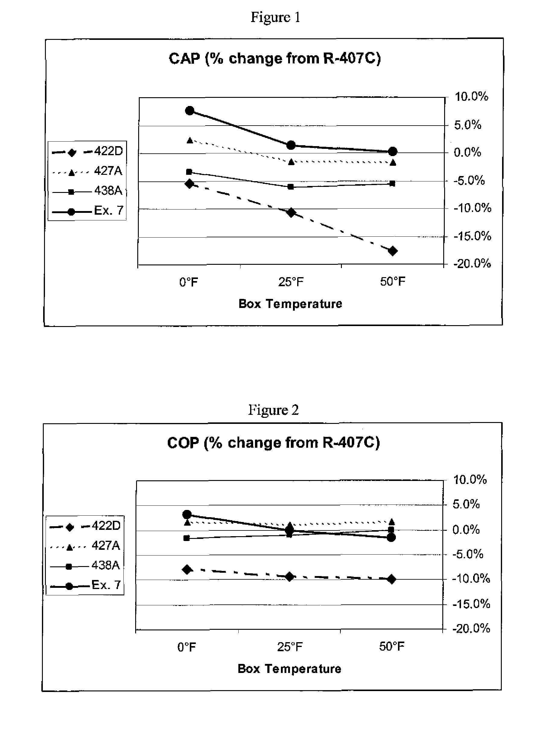
[0100]The refrigeration system was operated as in Comparative Example 3 except the refrigerant was a blend of about 21% R-32, 25% R-125, 22% R-1234yf, and 32% R-134a by weight (Ex. 7). There was satisfactory oil return at all conditions. For each box temperature, the capacity, relative to R-22, and the COP are given in Table 7.

[0101]FIG. 1 shows a comparison of the CAP for R-422D, R-427A, R-438A, and Ex. 7 relative to the CAP of R-407C. The capacity of Ex. 7 was greater than that of the other R-22 replacements at all conditions tested, particularly at the lower box temperatures.

[0102]FIG. 2 shows a comparison of the COP for R-422D, R-427A, R-438A, and Ex. 7 relative to the COP of R-407C. The COP of Ex. 7 was significantly higher than that of R-422D and close to that of R-407C, R-438A, and R-427A at 25° F. and 50° F. box temperatures. At 0° F. box temperature, Ex. 7 had a greater COP than R-407C, R-427A, R-43 8A, or R-422D.

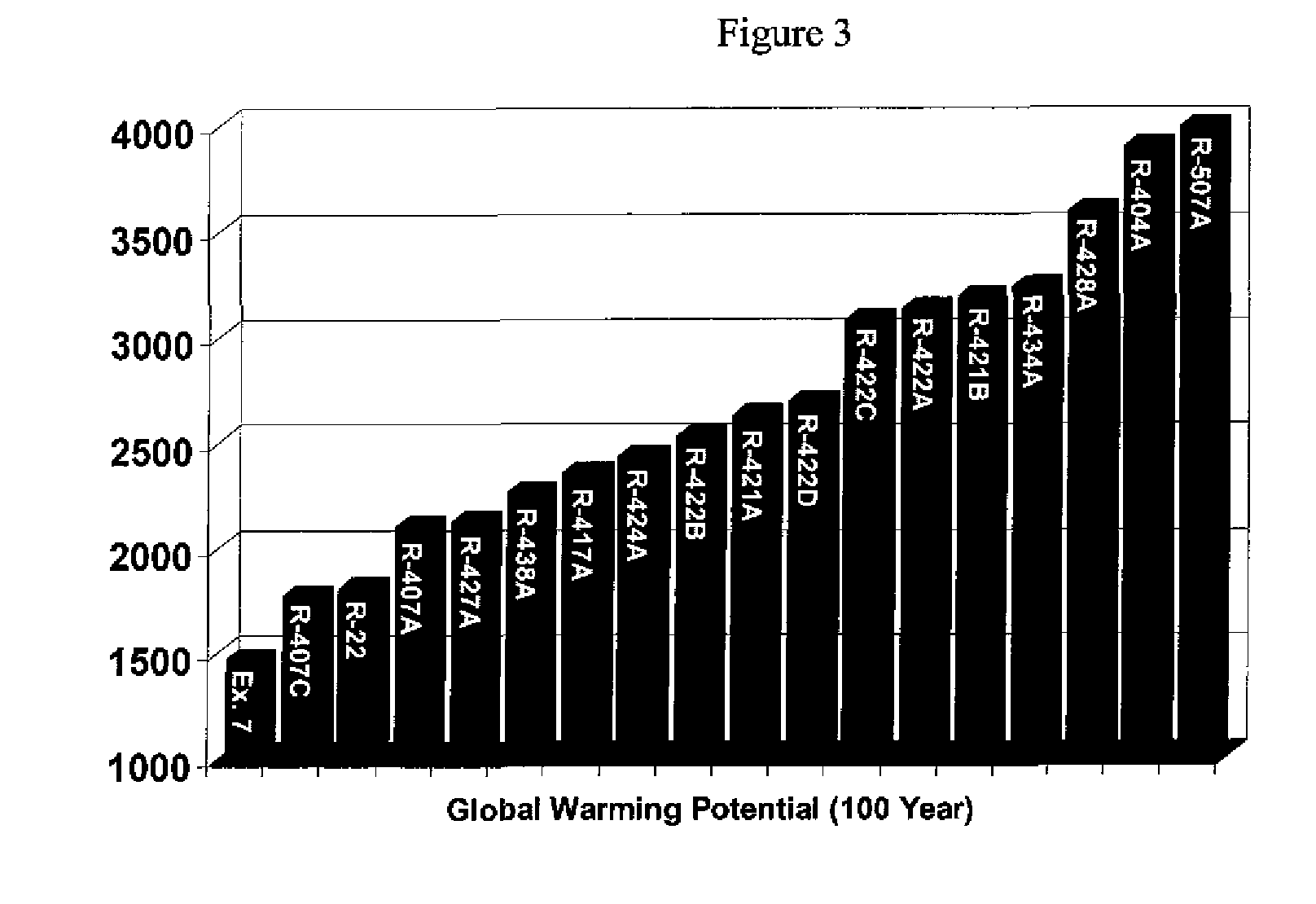
[0103]FIG. 3 shows the calculated GWP for R-22, Ex. 7, and nu...

example 8

R-22 Retrofits with Mineral Oil

[0104]Using mineral oil as the lubricant (National 150 Refrigeration Oil), the refrigeration equipment was charged with the refrigerant of Example 7, containing about 21% R-32, 25% R-125, 22% R-1234yf, and 32% R-134a. The system was operated at an ambient (condenser-side) temperature of 100° F. and a box (evaporator-side) temperature of 50° F. There was satisfactory oil return during stable operation.

[0105]The same evaluation was performed with R-422D, R-438A, and R-427A. In these cases the oil return was poor, where the oil level in the compressor dropped below OEM guidelines.


PUM

PropertyMeasurementUnit
wt %aaaaaaaaaa
wt %aaaaaaaaaa
wt %aaaaaaaaaa

Abstract

The present invention relates to heat transfer compositions comprising 2,3,3,3-tetrafluoropropene, difluoromethane, pentafluoroethane, and 1,1,1,2-tetrafluoroethane for use in refrigeration, air-conditioning, heat pump systems, and other heat transfer applications. The inventive heat transfer compositions can possess reduced global warming potential while providing good capacity and performance.

Description

FIELD OF THE INVENTION[0001]The present invention relates to heat transfer compositions comprising 2,3,3,3-tetrafluoropropene, difluoromethane, pentafluoroethane, and 1,1,1,2-tetrafluoroethane for use in refrigeration, air-conditioning, heat pump systems, and other heat transfer applications. The inventive heat transfer compositions can possess reduced global warming potential while providing good capacity and performance.BACKGROUND OF INVENTION[0002]With continued regulatory pressure there is a growing need to identify more environmentally sustainable replacements for refrigerants, heat transfer fluids, foam blowing agents, solvents, and aerosols with lower ozone depleting and global warming potentials. Chlorofluorocarbon (CFC) and hydrochlorofluorocarbons (HCFC), widely used for these applications, are ozone depleting substances and are being phased out in accordance with guidelines of the Montreal Protocol.[0003]Hydrofluorocarbons (HFC) are a leading replacement for CFCs and HCFC...

Claims


Application Information

Patent Timeline
Patent Type & Authority Applications(United States)
IPC IPC(8): C09K5/00
CPCC09K5/045C09K5/00C09K2205/22C09K2205/126C08J9/146C09K3/00C09K3/30C09K2205/43C09K2205/122
Inventor RACHED, WISSAMVAN HORN, BRETT L.SPLETZER, STEPHEN
Owner ARKEMA INC
Why Eureka
Try Eureka