
RF biometric ignition control system

a biometric ignition control and control system technology, applied in the direction of engine starters, anti-theft devices, instruments, etc., can solve the problems of inability to secure vehicle systems with biometric sensors, controls, and inability to use biometric sensors

Active Publication Date: 2013-04-18
PANASONIC AUTOMOTIVE SYST OF AMERICA
View PDF6 Cites 34 Cited by
  • Summary
  • Abstract
  • Description
  • Claims
  • Application Information

AI Technical Summary

Benefits of technology

The RF Biometric Ignition Control System (RBICS) is a remote control biometric-based ignition system that can be used to start any engine with an RF receiver connected to its ignition switch. The system uses a finger print sensor, skin texture / color sensor, or iris optic nerve sensor for biometric identification. This system helps solve the problem of remote control security for ignition systems.

Problems solved by technology

However, applications of biometric sensors have not yet made it to the vehicle market due to difficulty in integrating biometric sensors into the vehicle environment and due to the need to meet quality assurance guidelines.
Consequently, there is no secure vehicle system with biometric sensor capability at the present time.
Currently, there are no biometric sensors and controls for vehicles.
Biometric sensors of any kind, such as facial scanners, retina scanners, fingerprint sensors, hand scanners and DNA scanners, have not yet been made to meet automotive quality specifications.
One problem is that vehicle applications for biometric sensors are not very secure.
Known ignition devices are on the steering column or ignition switch and do not provide security.
There are no known ignition devices that include remote control with built-in biometric security.

Method used


Image

  • RF biometric ignition control system
  • RF biometric ignition control system
  • RF biometric ignition control system

Examples


Embodiment Construction

[0020]This section is intended to introduce the reader to various aspects of art which may be related to various aspects of the present invention which are described and / or claimed below. This discussion is believed to be helpful in providing the reader with background information to facilitate a better understanding of the various aspects of the present invention. Accordingly, it should be understood that these statements are to be read in this light, and not as admissions of prior art.

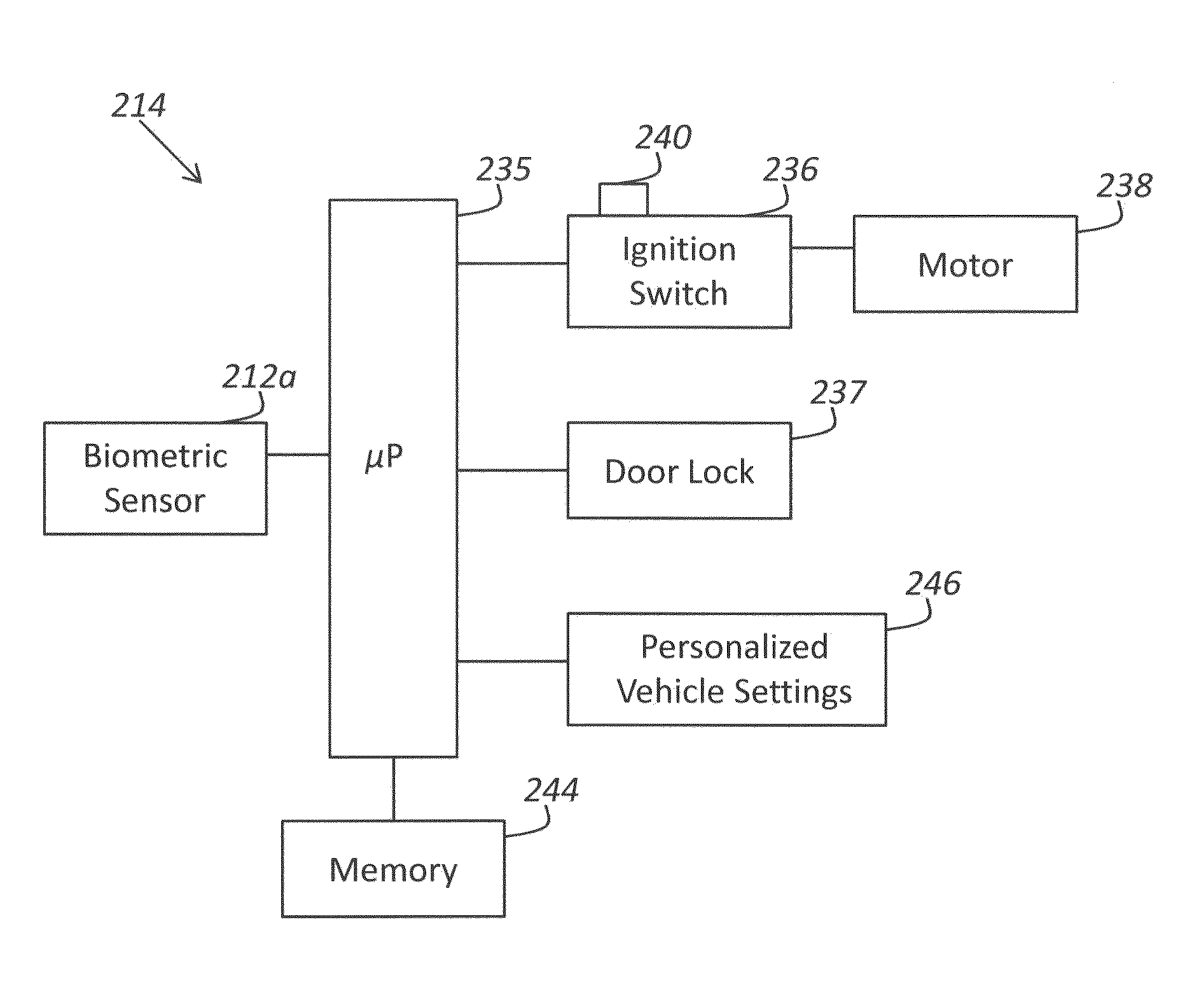
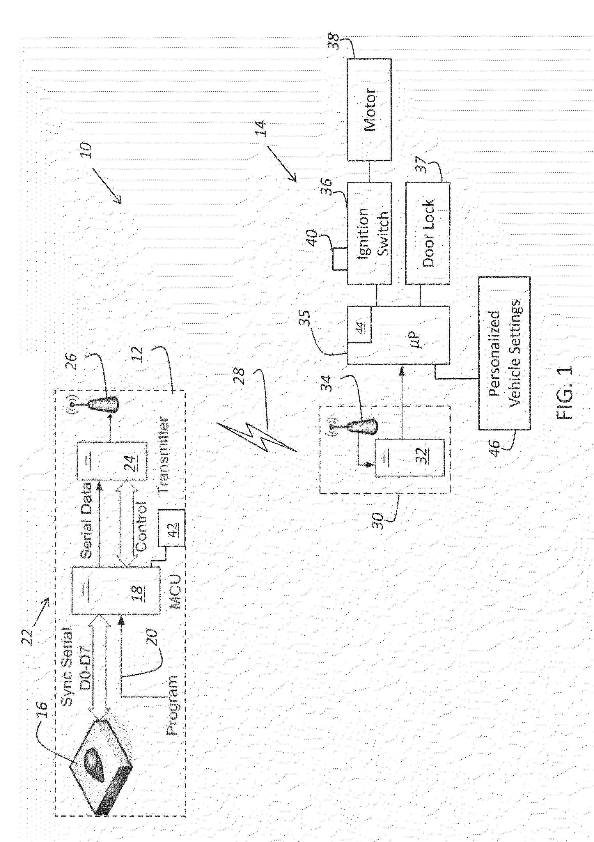
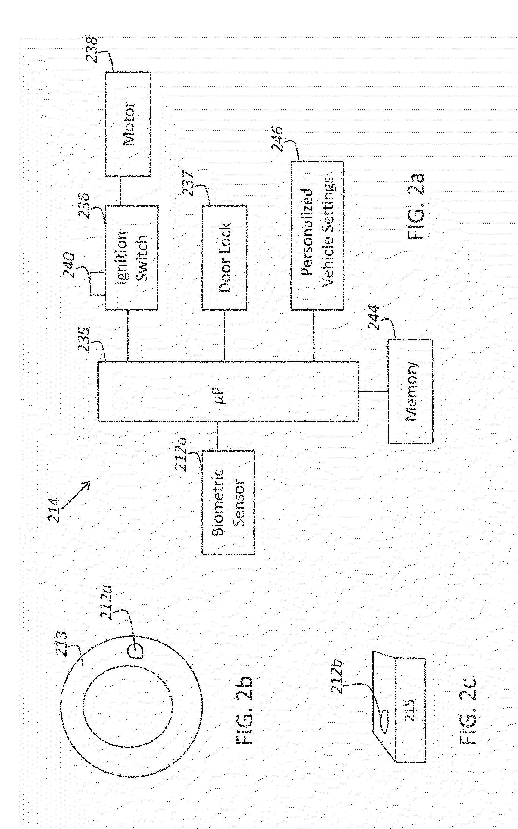
[0021]In the exemplary embodiment of the present invention in FIG. 1, there is shown an electronic ignition control system 10 including a keyfob 12 and vehicle 14. Keyfob 12 includes a biometric sensor 16 for sensing an identifying biological characteristic of a user or driver of vehicle 14. In the particular embodiment shown in FIG. 1, sensor 16 is in the form of a fingerprint sensor 16. Fingerprint sensor 16 may be a model, number AES2510 fingerprint sensor marketed by AuthenTec, Inc. of Melbourne,...


PUM


Abstract

An electronic ignition control system includes a keyfob having a biometric sensor that senses an identifying biological characteristic of the user. The keyfob also has a transmitter that transmits an air-borne signal dependent upon the identifying biological characteristic. A vehicle includes a motor and an ignition that starts the motor. The ignition has an unlocked state in which the user can cause the ignition to start the motor by actuating a start mechanism. The ignition also has a locked state in which actuation of the start mechanism by the user does not cause the ignition to start the motor. The vehicle also has a receiver that receives the air-borne signal from the transmitter. The vehicle further has a controller in communication with each of the ignition and the receiver. The controller switches the ignition from the locked state to the unlocked state dependent upon the air-borne signal received by the receiver.

Description

FIELD OF THE INVENTION[0001]The present invention generally relates to an ignition control system. In particular, the present invention relates to an ignition control system that verifies the identity of the user before unlocking the ignition system.BACKGROUND OF THE INVENTION[0002]Biometric sensors are rapidly developing. However, applications of biometric sensors have not yet made it to the vehicle market due to difficulty in integrating biometric sensors into the vehicle environment and due to the need to meet quality assurance guidelines. Consequently, there is no secure vehicle system with biometric sensor capability at the present time. In vehicles of today, once the door is open, any user can drive the car. Currently, there are no biometric sensors and controls for vehicles.[0003]Biometric sensors of any kind, such as facial scanners, retina scanners, fingerprint sensors, hand scanners and DNA scanners, have not yet been made to meet automotive quality specifications. One pro...

Claims


Application Information

Patent Timeline
IPC IPC(8): F02N11/08G06F19/00
CPCF02N11/0807G06K9/00838G06K9/00255B60R25/25G06V40/166G06V20/593B60R25/04B60R25/252
Inventor MANOTAS, JR., JESUS
Owner PANASONIC AUTOMOTIVE SYST OF AMERICA
Learn More