Vehicular wheel cover

a technology of vehicle wheel cover and wheel hub, which is applied in the direction of mechanical control devices, instruments, process and machine control, etc., can solve the problems of many aerodynamic inefficiencies associated with the rotating wheel of a traditional automotive vehicle, creating drag on the vehicle, and turbulent air flow, so as to reduce the air turbulence of the circumferential wheel hub and the wheelhouse. , the effect of reducing the air turbulence of the wheel hub

Inactive Publication Date: 2013-04-18
APTERA MOTORS
View PDF6 Cites 47 Cited by
  • Summary
  • Abstract
  • Description
  • Claims
  • Application Information

AI Technical Summary

Benefits of technology

[0004]In accordance with the present invention, an automotive vehicle wheel apparatus includes a turnable cover or door for a front wheelhouse opening in a fender. In another aspect, a sheath or liner is provided close to at least half of a circumference of a wheel. A further aspect blocks and / or removes circumferential air moving with a wheel. Yet another aspect connects an actuator adjacent a front and / or rear edge of a wheel cover so as to turn the cover with the wheel. In still another aspect, an electronic controller causes turning of a cover with a wheel. A method of operating an automotive vehicle, including reducing aerodynamic turbulence, is also provided.
[0005]The present apparatus is advantageous over traditional approaches. For example, the present apparatus reduces circumferential wheel air turbulence. Additionally, the present apparatus reduces wheel hub and wheelhouse opening air turbulence. The present apparatus also advantageously provides a much simpler, more cost effective, smaller and lighter weight mechanism to turn a wheel covering door. These aerodynamic and weight saving benefits are ideally suited for electrically driven vehicles in order to improve their operating range or distance for a given amount of stored energy. Additional features and advantages of the present apparatus can be ascertained from the following description and appended claims.

Problems solved by technology

There are many aerodynamic inefficiencies associated with rotating wheels of a traditional automotive vehicle.
For example, a ball of high pressure turbulent air is created at the front of each wheel where it meets the road thereby creating drag on the vehicle.
Furthermore, the wheelhouse, wheel rim and wheelhouse opening in the fender also cause turbulent air flow.
It is noteworthy that increases in conventional wheelhouse depth increase the total drag and total downforce, while conventional rotating wheels generate lift and considerable drag.
Therefore, it is believed that traditional wheels cause about eight percent of the total vehicle drag.
This is especially problemmatic as greater vehicular fuel efficiency and energy range are desired.
These traditional devices, however, are very complicated, undesirably take up space, and add significant weight through additional rods, turnbuckles and bars which defeat fuel savings due to aerodynamic improvements; some of these attempt to mechanically move a center of an apron or skirt which is geometrically difficult especially due to wind resistance at high speeds.
Moreover, traditional devices still do not reduce much of the circumferential aerodynamic turbulence caused by the wheel rotation.

Method used


Image

  • Vehicular wheel cover
  • Vehicular wheel cover
  • Vehicular wheel cover

Examples


Embodiment Construction

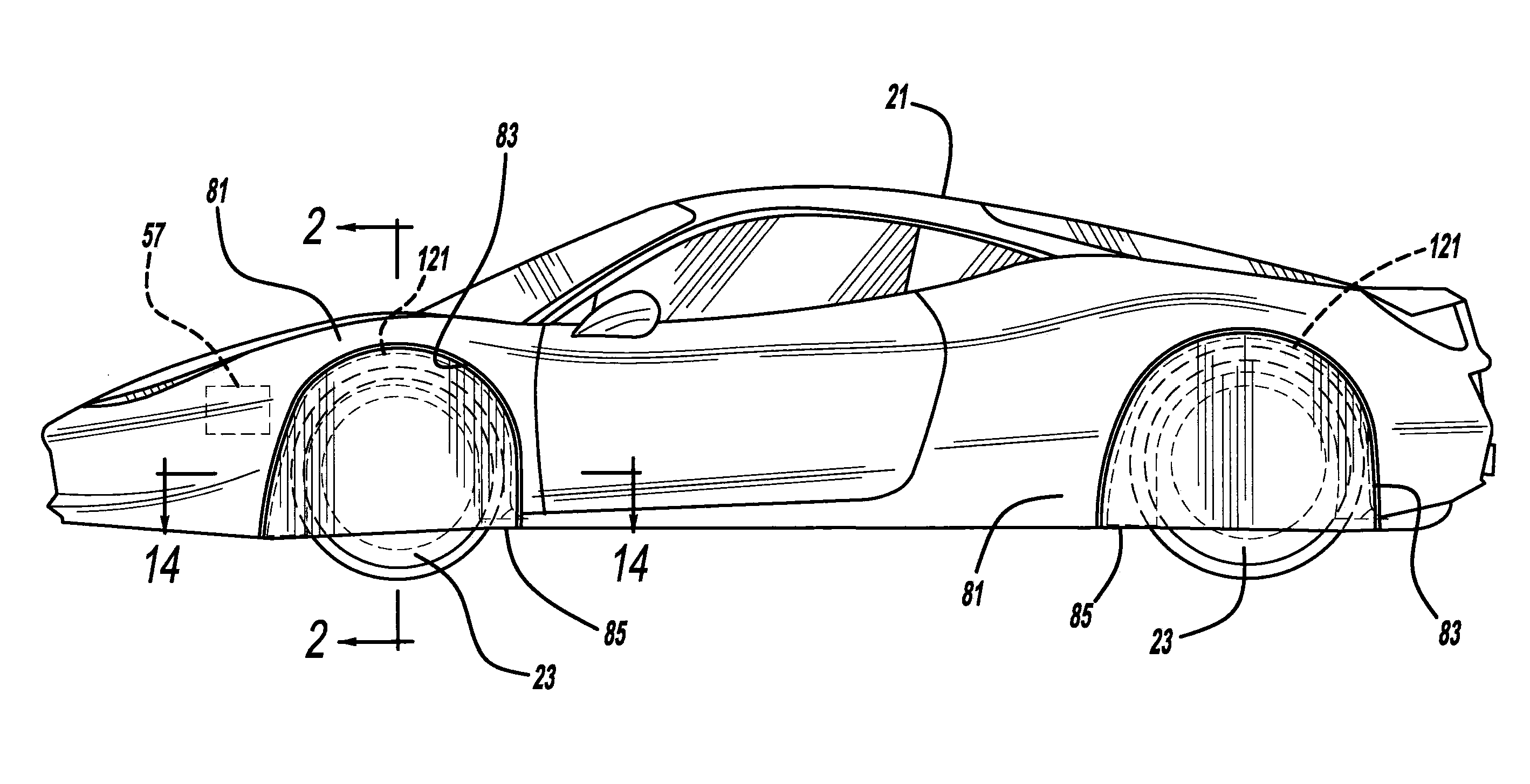
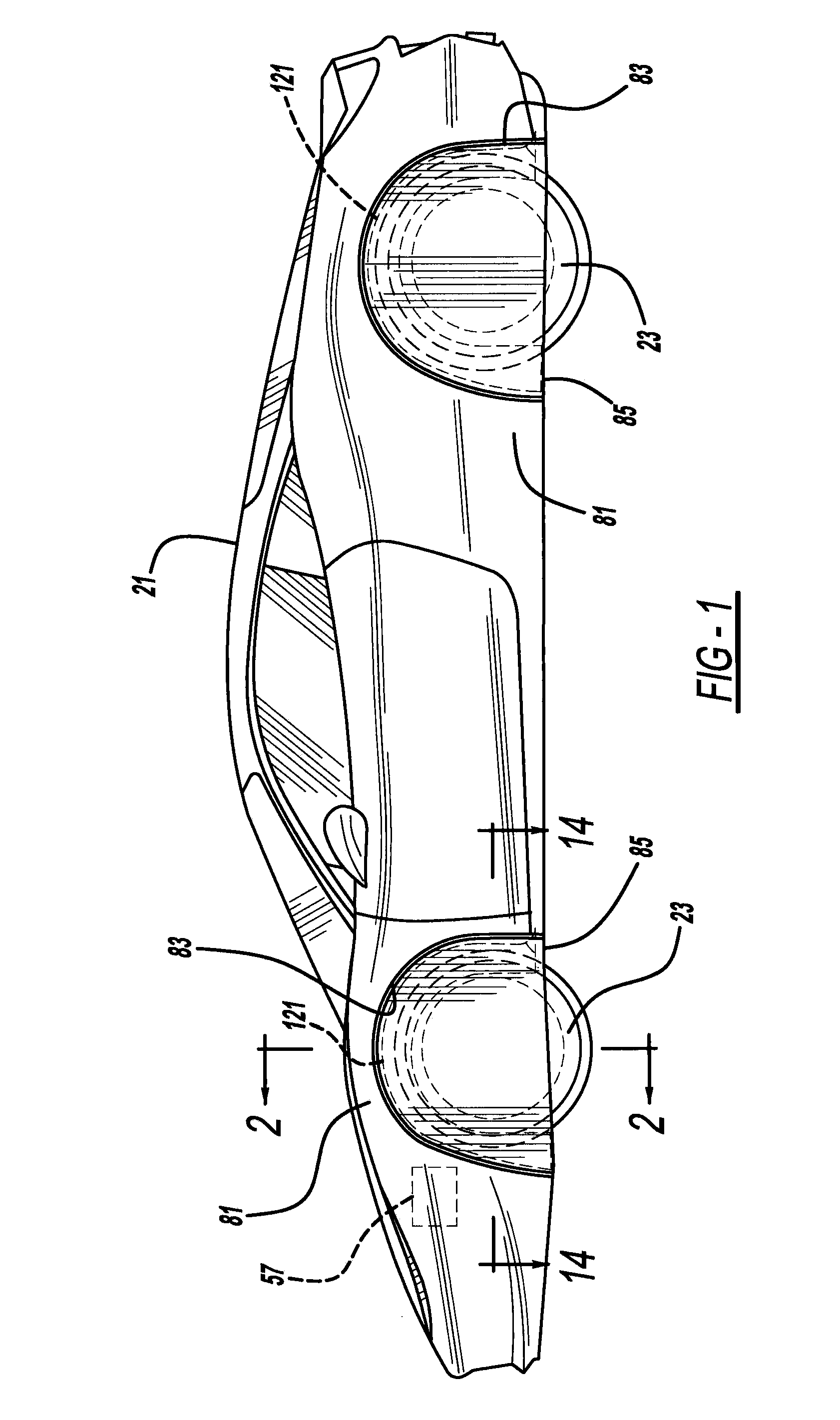
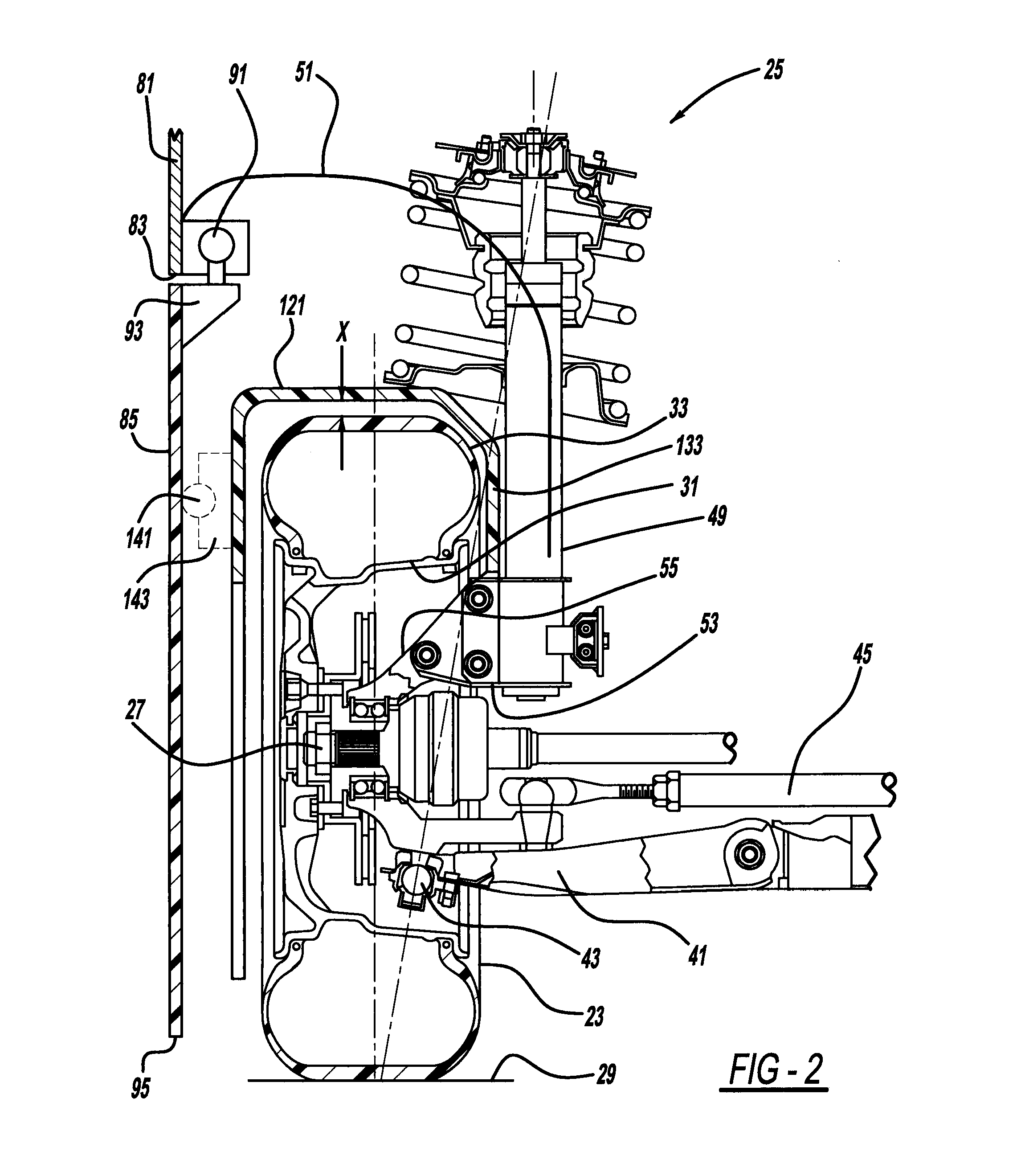
[0020]Referring to FIGS. 1-5, an automotive vehicle 21 having multiple passenger seats includes three or four wheels 23 each rotatable about a central hub 27 against a road surface 29. Each wheel includes a rigid metal rim 31 about which is mounted an inflated rubber tire 33. Each wheel is either powered or passive, while each wheel may also be steered or unsteerable, depending upon the vehicular configuration desired. In the specific vehicular configuration shown, the front two wheels are steerable and powered, and the rear two wheels are unsteerable and passive. A lower control arm 41 is coupled to wheel 23 by way of a knuckle 43. Furthermore, a tie rod 45 is coupled to an upright 55 and is either mechanically moved by turning of a steering column or through a motorized actuator, in response to steering wheel rotation by the vehicle driver. A suspension 25 is preferably a MacPherson strut 49 but may alternately employ a torsion bar, leaf spring or other mechanism to allow vertical...


PUM


Abstract

An automotive vehicle wheel apparatus includes a turnable cover or door for a wheelhouse opening in a fender. In another aspect, a sheath or liner is provided close to at least half of a circumference of a wheel. A further aspect blocks and/or removes circumferential air moving with a wheel.

Description

BACKGROUND AND SUMMARY[0001]The present invention relates generally to automotive vehicle aerodynamics and more particularly to an apparatus associated with an automotive vehicle wheel.[0002]There are many aerodynamic inefficiencies associated with rotating wheels of a traditional automotive vehicle. For example, a ball of high pressure turbulent air is created at the front of each wheel where it meets the road thereby creating drag on the vehicle. Furthermore, the wheelhouse, wheel rim and wheelhouse opening in the fender also cause turbulent air flow. For example, turbulent air flow vortices are caused by separation of an air boundary layer developed at outer edges of a conventional wheelhouse arch. A downward air flow is also present in front of the conventional rotating wheel; this causes a high pressure region or ball of air at the wheel-to-road contact point. A strong C-shaped vortex is originated by the interaction of downward flow and the separation of a lateral flow of a bo...

Claims


Application Information

Patent Timeline
Patent Type & Authority Applications(United States)
IPC IPC(8): B62D25/18G06F7/00B60Q1/00G05G1/04
CPCB62D25/18G06F7/00Y10T74/20B60Q1/326G05G1/04B62D25/182
Inventor REICHENBACH, THOMAS GEORGEWILBUR, PAUL BERINGERMCCAMMON, MARQUES
Owner APTERA MOTORS
Why Eureka
Try Eureka