Processing method and processing device for concave-convex gear

a processing method and concave-convex gear technology, applied in the direction of gear teeth, manufacturing tools, gear grinding, etc., can solve the problem of difficult machining, achieve the effect of reducing size, improving the meshing rate of mating gear and concave-convex gear, and easy machine the concave teeth

Active Publication Date: 2013-04-25
JTEKT CORP
View PDF46 Cites 7 Cited by
  • Summary
  • Abstract
  • Description
  • Claims
  • Application Information

AI Technical Summary

Benefits of technology

[0068]With the invention according to claim 1 configured as described above, an NC machine tool is used to make it possible to machine the concave teeth of the concave-convex gear. That is, the same NC machine tool may be used to machine concave-convex gears having various shapes. Specifically, an NC program is generated on the basis of the relative movement trajectory extracted in the trajectory extracting step, and the concave teeth of the concave-convex gear may be machined in the machining step using the NC program. In this way, it is possible to extremely easily machine the concave teeth of the concave-convex gear.
[0069]Here, in the concave-convex gear that rotates about an intersecting axis with respect to a mating gear (hereinafter, also referred to as “concave-convex gear with an intersecting axis”), the meshing rate of the mating gear and the concave-convex gear increases. Therefore, it is possible to reduce size, increase strength and achieve quietness. On the other hand, in order to achieve desirable tooth contact, it is required to form a tooth flank shape having an extremely high accuracy, so there is a problem that machining of a tooth flank shape is not easy. In contrast to this, with the invention according to claim 2, the concave teeth of the concave-convex gear with an intersecting axis may be easily and highly accurately formed. As a result, according to the invention, it is possible to reduce machining cost in the case of accuracy equivalent to the existing art. Note that, other than the concave-convex gear with an intersecting axis, the invention may be applied to a concave-convex gear with a parallel axis, that is, a so-called spur gear.
[0070]With the invention according to claim 3, because the number of teeth of the mating gear is different from the number of teeth of the concave-convex gear, so it is configured such that torque is transmittable while the mating gear and the concave-convex gear perform differential rotation. Then, because the number of teeth is different therebetween, the shape of each concave tooth of the concave-convex gear is an extremely complex shape. In such a case as well, by applying the invention, it is possible to reliably machine the concave teeth of the concave-convex gear. Note that, when the number of teeth of the mating gear is equal to the number of teeth of the concave-convex gear, that is, when torque is transmitted while rotating at the same number of revolutions as well, the machining method according to the invention is, of course, applicable.
[0071]With the invention according to claim 4, although the relative movement between the concave-convex gear and the mating gear is three-dimensional complex movement, the reference axis is used to make it possible to reliably understand the relative movement trajectory. Here, the reference conical surface is a surface that passes through the reference pitch circle of each cross section. The case where a cone angle of 0° or a cone angle of 180° is included. In addition, the tooth thickness central plane of each convex tooth of the mating gear means the central plane of each convex tooth in a circumferential width.
[0072]With the invention according to claim 5, the sectional shape of each convex tooth of the mating gear in the direction orthogonal to the reference axis is a circular arc shape. By so doing, the mating gear and the concave-convex gear are able to extremely smoothly transmit torque. On the other hand, machining of the concave teeth of the concave-convex gear becomes complicated. Because the sectional shape of each convex tooth of the mating gear in the direction orthogonal to the reference axis is a circular arc shape, each concave tooth of the concave-convex gear has a sectional shape approximate to a circular arc concave shape as a whole, and, specifically, has a sectional shape of which the opening edge portions of the circular arc concave shape are sagged. In this way, even when each concave tooth of the concave-convex gear has a complex shape, the invention is applied to make it possible to reliably and highly accurately perform machining. As a result, it is possible to form the nutation gear 15 having high performance at low cost. Note that, even when each convex tooth of the mating gear is formed in a shape other than a pin shape, the machining method of the invention may be applied.
[0073]With the invention according to claim 6, by using the disc-shaped tool to spuriously express a pin-shaped convex tooth, it is possible to reliably machine the concave teeth of the concave-convex gear. Furthermore, by using the disc-shaped tool, the stiffness of the tool may be enhanced, so it is possible to perform machining with high accuracy. With the invention according to claim 7, machining is performed on the basis of the position of the infeed operation, obtained through comparison between the ideal shape model and the simulation model, so it is possible to form the highly accurate concave teeth of the concave-convex gear.

Problems solved by technology

The nutation gear has an extremely complex meshing face that meshes with the first gear or the second gear, so machining is not easy.

Method used


Image

  • Processing method and processing device for concave-convex gear
  • Processing method and processing device for concave-convex gear
  • Processing method and processing device for concave-convex gear

Examples


first embodiment

[0103]Six-Axis Configuration (Three Linear Axes and Three Rotation Axes)

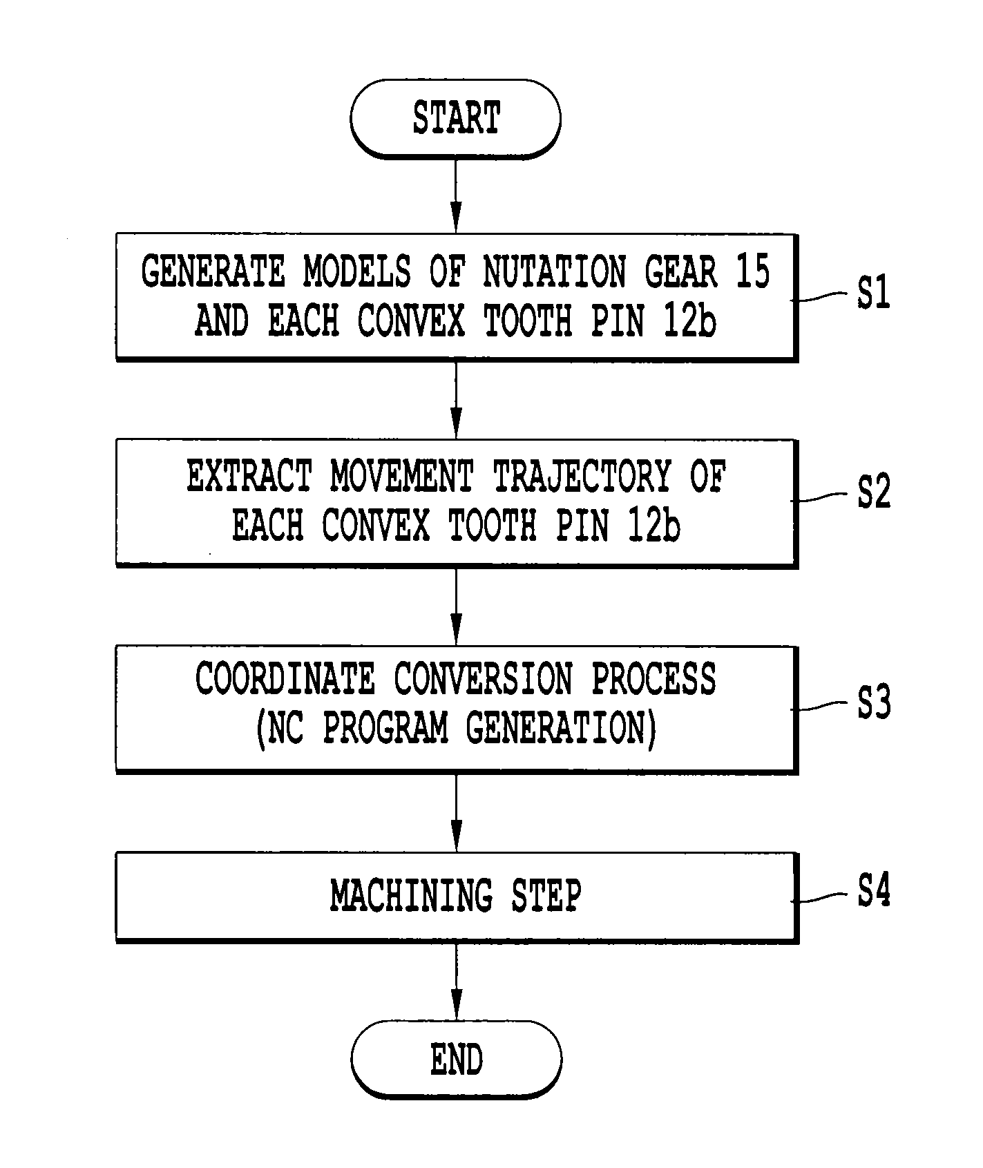
[0104]A machining method and machining device for a nutation gear of a nutation gear set according to a first embodiment will be described with reference to FIG. 1 to FIG. 10. The machining device in the present embodiment shows the case of a six-axis configuration having three orthogonal linear axes and three rotation axes.

[0105](1) Configuration of Nutation Gear Set

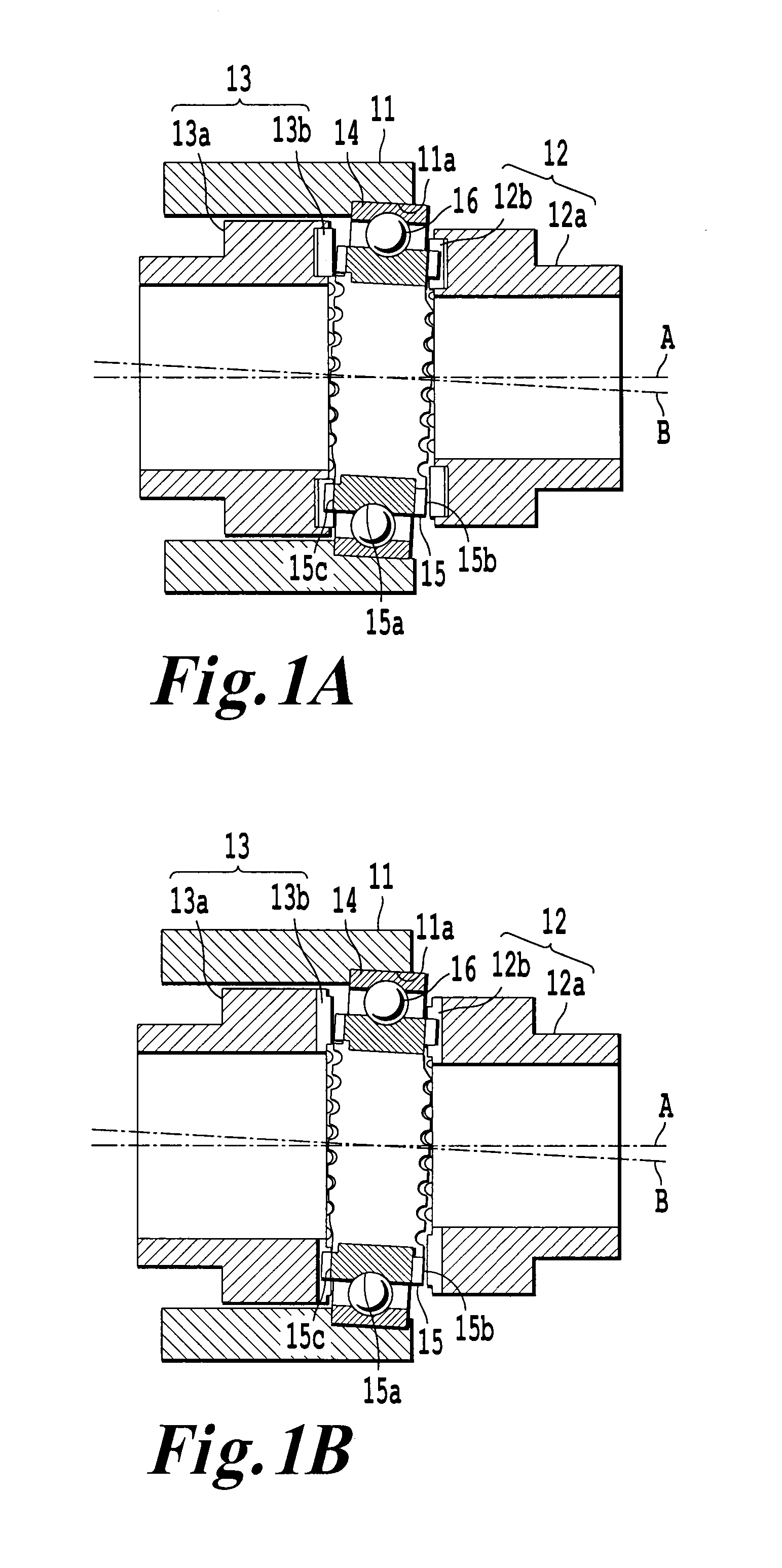
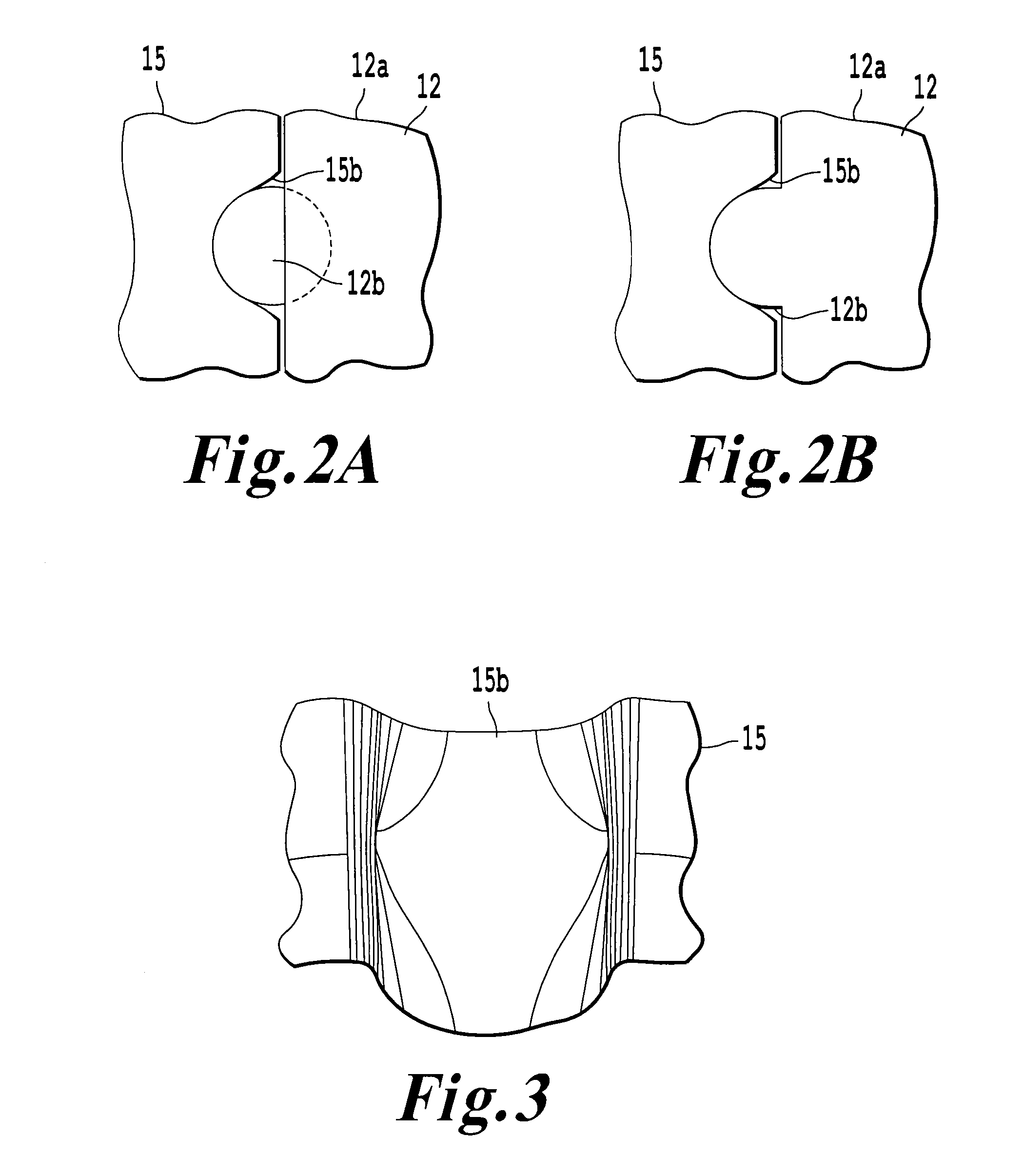
[0106]The configuration of the nutation gear set that uses the nutation gear that is a machining object of the invention will be described with reference to FIG. 1 to FIG. 4. Here, FIG. 1(a) shows a case where convex tooth pins 12b and 13b are respectively separately formed from a fixed shaft body 12a and an output shaft body 13a, and FIG. 1(b) shows a case where the convex tooth pins 12b and 13b are respectively integrally formed with the fixed shaft body 12a and the output shaft body 13a. Note that, hereinafter, description will be made mainly wit...

second embodiment

Five-Axis Configuration (Three Linear Axes and Two Rotation Axes) (First Example of Omission of Fourth Rotation Axis)

[0151]A machining method and machining device for a nutation gear of a nutation gear set according to a second embodiment will be described with reference to FIG. 11. The machining device in the present embodiment shows the case of a five-axis configuration having three orthogonal linear axes and two rotation axes. The fourth rotation axis in the first embodiment is omitted. Specifically, movement along the fourth rotation axis described in the first embodiment is decomposed into movement along the sixth indexing axis and movement along the third linear axis.

[0152]Here, in the present embodiment, “model generation” (S1) and “trajectory extracting step” (S2) in the first embodiment are the same. That is, the movement trajectory of the convex tooth pin 12b, extracted in the trajectory extracting step, is expressed by the three linear axes and the three rotation axes.

[01...

third embodiment

Five-Axis Configuration (Three Linear Axes and Two Rotation Axes) (Second Example of Omission of Fourth Rotation Axis)

[0157]A machining method and machining device for a nutation gear of a nutation gear set according to a third embodiment will be described with reference to FIG. 12. The machining device in the present embodiment shows the case of a five-axis configuration having three orthogonal linear axes and two rotation axes. The fourth rotation axis in the first embodiment is omitted. Specifically, movement along the fourth rotation axis described in the first embodiment is decomposed into movement along the sixth indexing axis and movement along the second linear axis.

[0158]Here, in the present embodiment, “three-dimensional CAD model generation” (S1) and “trajectory extracting step” (S2) in the first embodiment are the same. That is, the movement trajectory of the convex tooth pin 12b, extracted in the trajectory extracting step, is expressed by the three linear axes and the...


PUM

PropertyMeasurementUnit
cone angleaaaaaaaaaa
torqueaaaaaaaaaa

Abstract

A trajectory extracting step of extracting a relative movement trajectory of each convex tooth pin of a mating gear with respect to a concave-convex gear at the time when torque is transmitted between the mating gear (fixed shaft) and the concave-convex gear (nutation gear) and a machining step of, when the concave-convex gear is machined on a concave tooth forming face of a disc-shaped workpiece on which the concave teeth have not been machined, moving at least one of the disc-shaped workpiece and a working tool such that a relative movement trajectory of the working tool with respect to the disc-shaped workpiece coincides with the relative movement trajectory of each convex tooth pin with respect to the concave-convex gear, extracted in the trajectory extracting step, are included.

Description

TECHNICAL FIELD[0001]The invention relates to a machining method and machining device for a concave-convex gear.BACKGROUND ART[0002]There is a nutation gear set as one of reduction gears. The nutation gear set is, for example, described in Patent Document 1. That is, the nutation gear set is formed of a first gear, a second gear and an input shaft that have the same rotation central axis, and a nutation gear that performs differential rotation with respect to the first gear and the second gear while wobbling therebetween. The nutation gear is supported by the input shaft so as to be rotatable about an inclined rotation central axis. Furthermore, the inclined rotation central axis relatively rotates about the rotation central axis of the first gear with the rotation of the input shaft. By so doing, the nutation gear wobbles with respect to the first gear and the second gear. Then, first nutation teeth that mesh with the first gear are formed on a face of the nutation gear, adjacent t...

Claims


Application Information

Patent Timeline
Patent Type & Authority Applications(United States)
IPC IPC(8): B23F15/00
CPCB23F15/00Y10T29/49467Y10T29/54F16H1/321
Inventor ANDO, YOSHIAKITAKESHIMA, MASAYUKIHIROTA, IKUKO
Owner JTEKT CORP
Why Eureka
Try Eureka