Percussion tool having cooling of equipment components

a technology of equipment components and cooling tools, which is applied in the direction of portable percussive tools, boring/drilling equipment, drilling machines and methods, etc., can solve the problems that the percussion mechanism driven by the combustion engine provided to generate the working movement of the hammer drill may also heat up intensely, so as to achieve the effect of improving the cooling

Inactive Publication Date: 2013-04-25
WACKER NEUSON SE
View PDF6 Cites 3 Cited by
  • Summary
  • Abstract
  • Description
  • Claims
  • Application Information

AI Technical Summary

Benefits of technology

[0027]The percussion mechanism may be a pneumatic percussion mechanism and exhibit a guide housing and also a drive piston movable by the combustion engine in the guide housing, e.g. in an oscillating and linear manner, wherein the second cooling air duct is used to conduct the second cooling air flow to an outer side of the guide housing. Correspondingly, the first duct section may also be designed to conduct the cooling air flow to the outer side of the guide housing. The heat in the percussion mechanism is generated particularly proximate to the air compression section within the percussion mechanism, when the percussion mechanism is a pneumatic percussion mechanism known per se. This heat is emitted outwardly via the guide housing and can be removed by the cooling air flow. Since the temperature occurring in the percussion mechanism is greater than the temperature of the engine cooling exhaust air, the engine cooling exhaust air can still be effectively used to cool the percussion mechanism.
[0028]In one variant, the second cooling air duct may be designed such that the second cooling air flow downstream of the percussion mechanism can still be conducted to the exhaust system of the combustion engine. It has therefore emerged that the cooling air still exhibits a temperature lower than the exhaust temperature of the combustion engine, particularly lower than the temperature of the sound damper belonging to the exhaust system, even when it has already cooled the engine (cylinder) and the percussion mechanism. For this reason, it may be advantageous for the cooling air still to be used to support cooling of the sound damper, after cooling of the percussion mechanism, so that the cooling effect is thereby improved.

Problems solved by technology

The percussion mechanism driven by the combustion engine provided to generate the working movement of the hammer drill may also heat up intensely due to the air compression, particularly when a pneumatic percussion mechanism is involved.

Method used


Image

  • Percussion tool having cooling of equipment components
  • Percussion tool having cooling of equipment components
  • Percussion tool having cooling of equipment components

Examples


Embodiment Construction

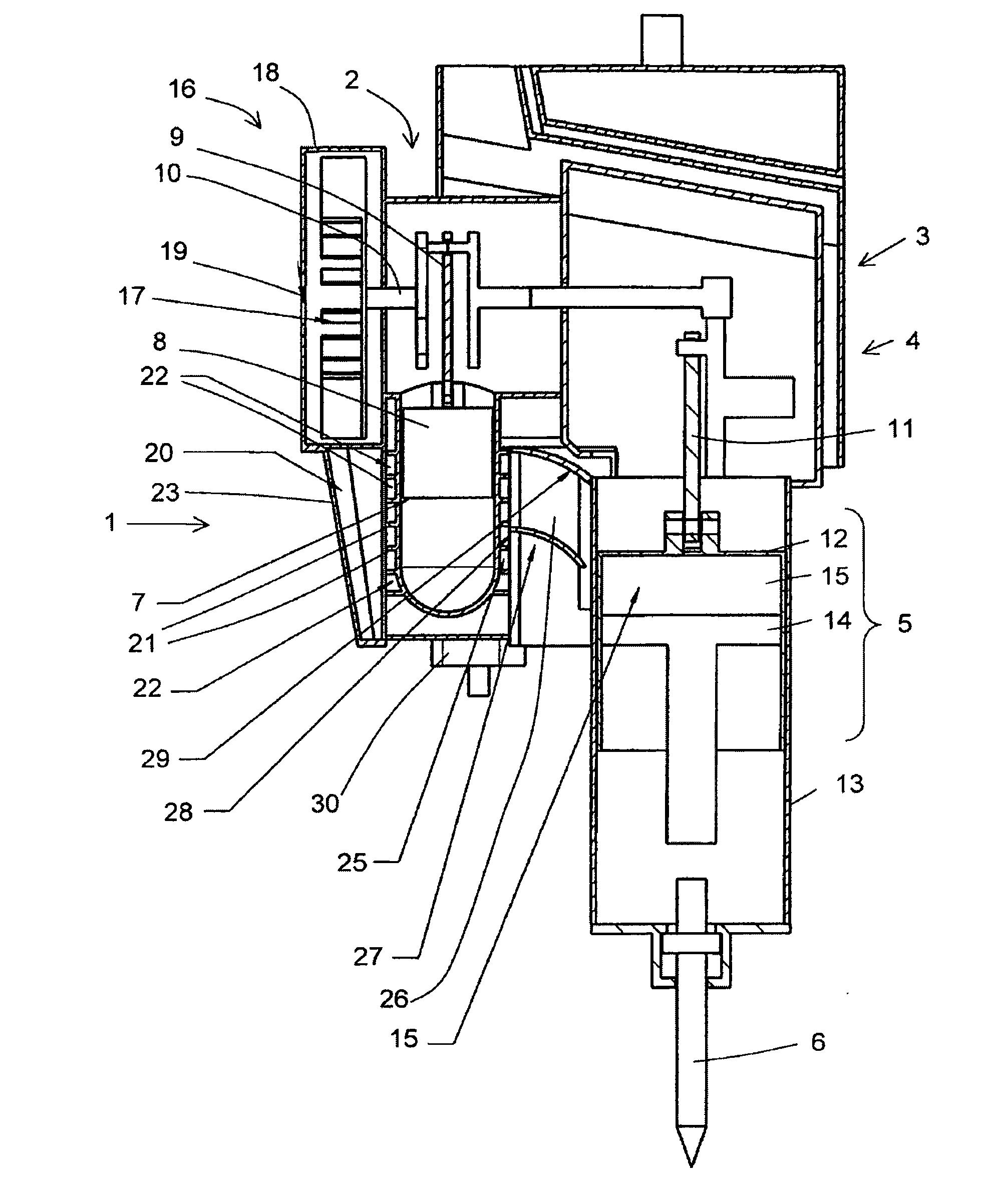
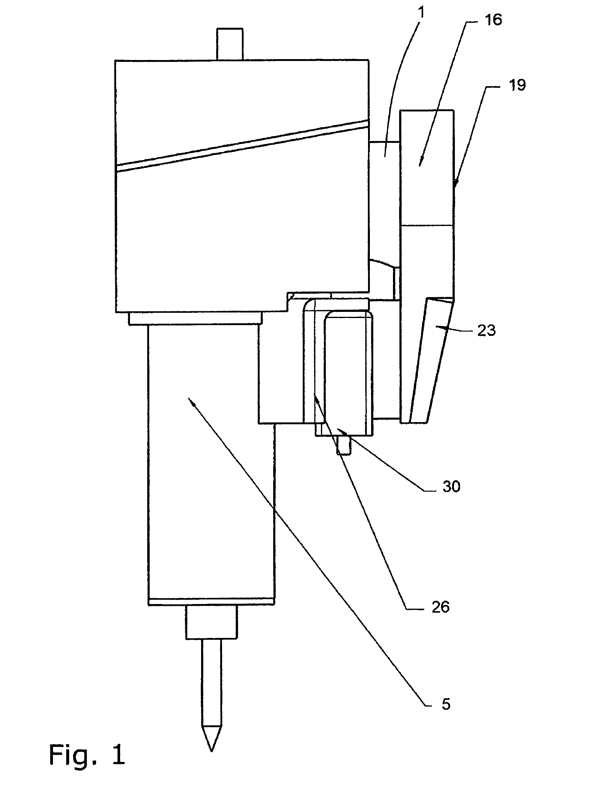
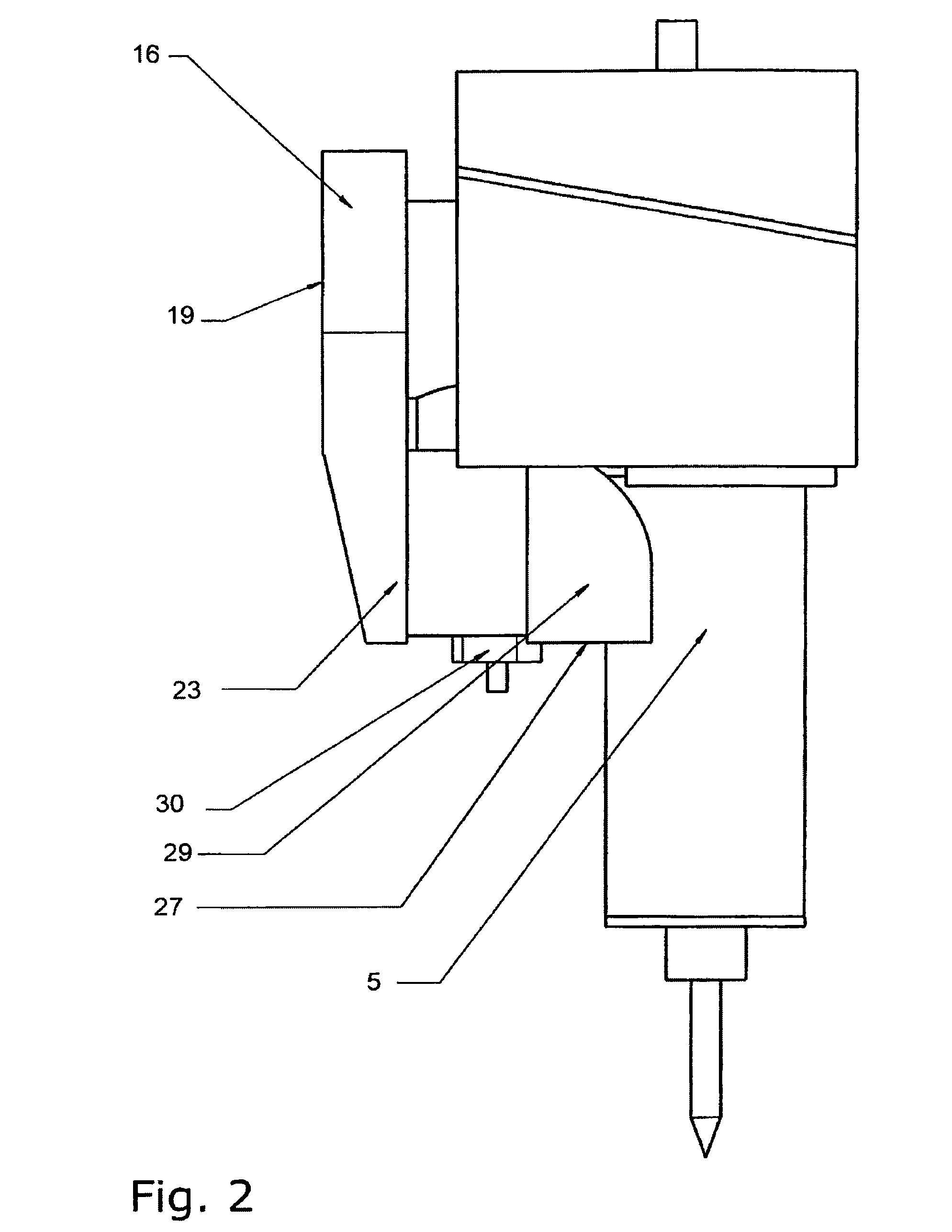
[0037]The hammer drill has a combustion engine 1, which drives a percussion mechanism 5 via a first crank mechanism 2, a gear 3 and a second crank mechanism 4. The percussion mechanism 5 in turn strikes a tool 6, in the present case a bit. The design of a hammer drill of this kind is widely known and need not therefore be explained in detail.

[0038]The combustion engine 1 has a cylinder 7, within which a piston 8 is movably conducted. The piston 8 drives the first crank mechanism 2 via a connecting rod 9.

[0039]The gear 3 and therefore the second crank mechanism 4 are moved via a crankshaft 10 of the crank mechanism 2.

[0040]The percussion mechanism 5 is in the form of a pneumatic percussion mechanism and has a connecting rod 11 moved by the second crank mechanism 4, which moves a drive piston 12 back and forth in a guide housing 13 belonging to the percussion mechanism.

[0041]A main piston 14 is conducted within the drive piston 12, said main piston moving towards the end of the tool 6...


PUM

PropertyMeasurementUnit
temperatureaaaaaaaaaa
flow rateaaaaaaaaaa

Abstract

A percussion tool has a cooling air channel for guiding a cooling air flow from a cooling air fan to an outside wall of a cylinder of an internal combustion engine. The cooling air channel is tapered to the extent that partial cooling air flows guided between the respective cooling fins are branched off the main cooling air flow. In such a way, the flow rate of the cooling air flow in the cooling air channel remains substantially constant, resulting in optimized engine cooling. The cooling air channel may be divided into two cooling air channels downstream of the cylinder. One of the cooling air channels guides cooling air to an exhaust gas system of the internal combustion engine, while the other cooling air channel guides cooling air to an outside wall of the guide housing of a hammer mechanism.

Description

BACKGROUND OF THE INVENTION[0001]1. Field of the Invention[0002]The invention relates to a percussion tool having a combustion engine.[0003]2. Discussion of the Related Art[0004]Percussion tools such as hammer drills and / or percussion hammer drills having a combustion engine—hereinafter referred to in short as hammer drills—are known in particular as relatively heavy breakers, which are essentially worked vertically in a downward direction. In petrol-powered hammer drills of this kind, a cooling air fan driven via the crankshaft of the combustion engine is provided for cooling the engine. The cooling air fan produces a cooling air flow which is conducted along the outside of the combustion engine cylinder, particularly along the cooling fins provided on the outside of the cylinder. The engine cooling exhaust air discharged from the engine is usually very hot in this case and must therefore be conducted away from the hammer drill by the shortest route.[0005]The percussion mechanism d...

Claims


Application Information

Patent Timeline
Patent Type & Authority Applications(United States)
IPC IPC(8): B25D17/20B25D9/10
CPCB25D9/10B25D2217/0061B25D2211/068B25D17/20
Inventor FISCHER, MICHAELSTENZEL, OTTO W.HAUSLER, WOLFGANGBERGER, RUDOLFLITTEK, CHRISTIANBRAUN, HELMUTZINSMEISTER, MANFRED
Owner WACKER NEUSON SE
Why Eureka
Try Eureka