
Manipulator carrier for electron microscopes

a technology for electron microscopes and manipulators, which is applied in the direction of machines/engines, liquid/fluent solid measurements, instruments, etc., can solve the problems of contaminating the chamber, limiting the space of the mobile microrobot, and unable to accommodate more than one manipulator in the specimen exchange chamber or the feedthrough

Active Publication Date: 2013-04-25
JIANGSU JICUI MICRO NANO AUTOMATION SYST & EQUIP TECH RES INST CO LTD
View PDF2 Cites 9 Cited by
  • Summary
  • Abstract
  • Description
  • Claims
  • Application Information

AI Technical Summary

Benefits of technology

The vacuum specimen chamber in this patent is designed to prevent contamination, which improves imaging performance. It also saves time because it does not need to be emptied for manipulator mounting. The design allows for easy use of the electron microscope for imaging and analysis, without interfering with the manipulation capabilities. This allows for flexibility in use of the electron microscope for both imaging and analysis without interfering with each other's work.

Problems solved by technology

Moreover, they both have the limitation that neither the specimen exchange chamber nor the feedthrough is able to accommodate more than one manipulator.
In comparison to fixed micromanipulators, this mobile microrobot has a larger workspace but a poorer positioning resolution.
End-effectors are changed frequently primarily because they are prone to damage (e.g., bending and breakage).
Since all existing SEM nanomanipulation systems are fastened inside the high-vacuum specimen chamber, exchanging end-effectors necessitates opening of the specimen chamber, which not only contaminates the chamber (thus worse imaging performance) but also incurs a lengthy, time-consuming pump-down process.

Method used


Image

  • Manipulator carrier for electron microscopes
  • Manipulator carrier for electron microscopes
  • Manipulator carrier for electron microscopes

Examples


Embodiment Construction

[0054]Unless defined otherwise, all technical and scientific terms used herein have the same meaning as commonly understood by one of ordinary skill in the art to which this invention belongs. Also, unless indicated otherwise, except within the claims, the use of “or” includes “and” and vice-versa. Non-limiting terms are not to be construed as limiting unless expressly stated or the context clearly indicates otherwise (for example “including”, “having” and “comprising” typically indicate “including without limitation”). Singular forms including in the claims such as “a”, “an” and “the” include the plural reference unless expressly stated otherwise. All publications cited in this document are incorporated herein by reference. The invention will be explained in details by referring to the figures.

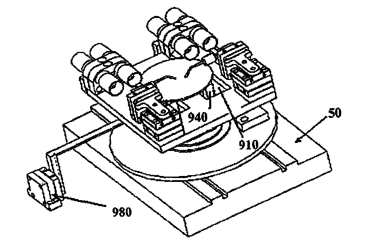
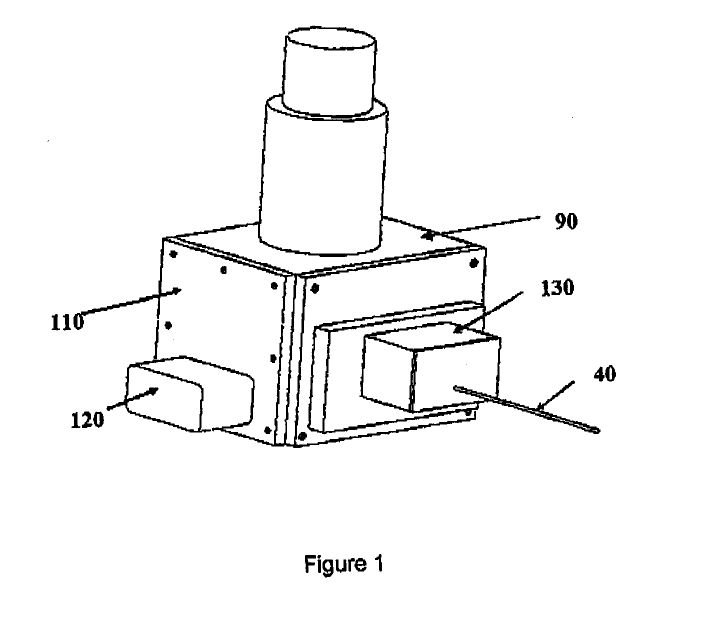
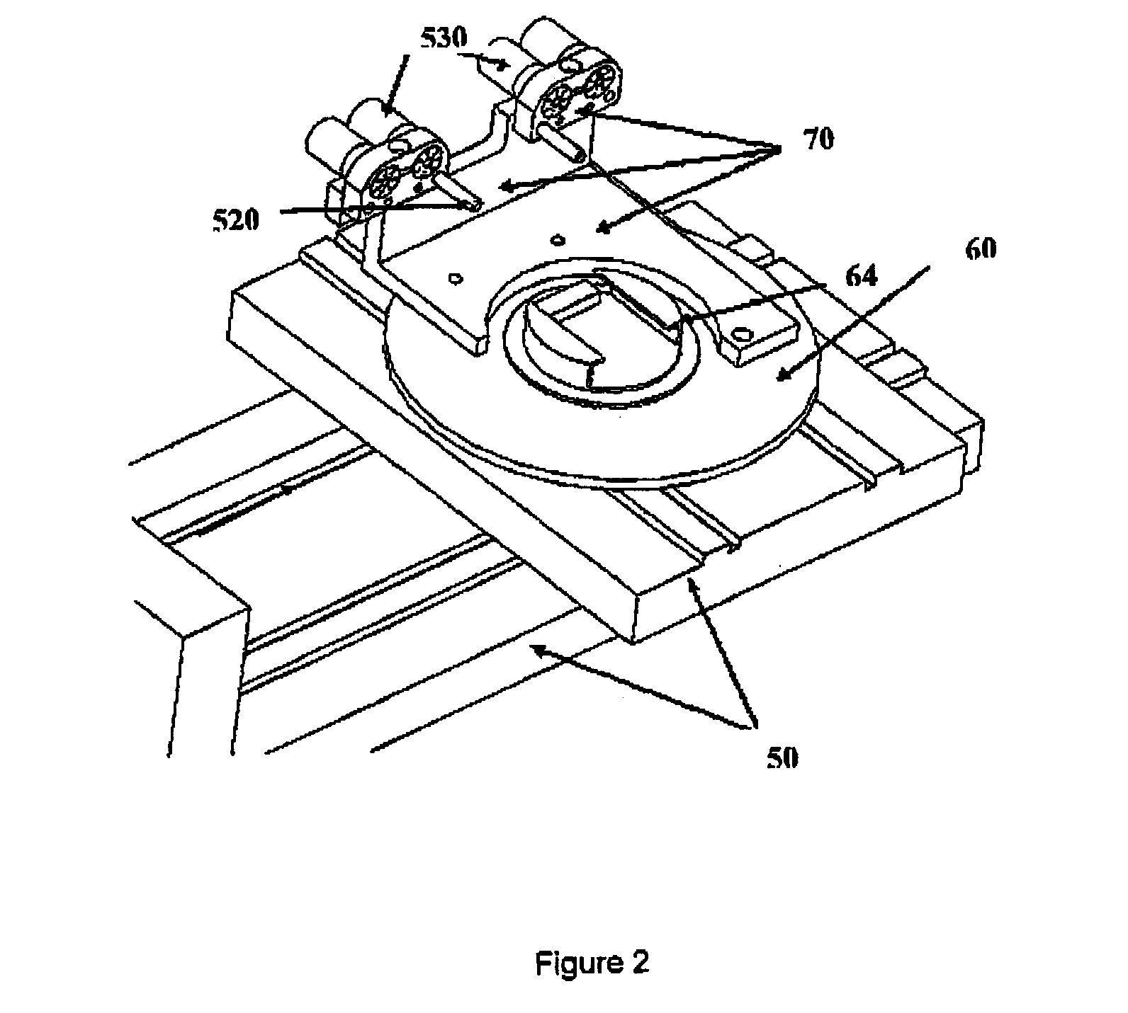
[0055]The present invention relates to devices, systems, and methods that allow the transport of one or more manipulators into and out of an electron microscope without disturbing the high va...


PUM


Abstract

The present invention relates to a carrier device for transporting one or more manipulators into a vacuum specimen chamber of an electron microscope, characterized in that the carrier device comprises: (i) a platform having securing means for detachably securing the one or more manipulators to the platform, and (ii) electrical connectors secured to the platform for the electrical connection of the one or more manipulators. The present invention also relates to a method for transporting the carrier device into the vacuum specimen chamber of the electron microscope without altering the vacuum of the vacuum specimen chamber comprising transporting the carrier device of the invention through the specimen exchange chamber of the electron microscope and into the vacuum specimen chamber.

Description

FIELD OF THE INVENTION[0001]The present invention relates to a system for the manipulation and testing of samples at the micrometer and nanometer scales inside an electron microscope. More particularly, the present invention relates to a manipulator carrier for electron microscopes, a system for transporting the manipulator carrier into the electron microscope and to methods of transporting the manipulator carrier of the invention into the electron microscope.BACKGROUND OF THE INVENTION[0002]Since scanning electron microscopy (SEM) provides an image resolution down to a few nanometers and a relatively high frame rate in comparison to atomic force microscopy, manipulators have been installed inside scanning electron microscopes (SEM) for the dissection, manipulation, or testing of samples at the nanometer scale. For instance, a nanomanipulator was built and used in tensile-loading individual carbon nanotubes inside an SEM in order to characterize their mechanical properties (M. -F. Y...

Claims


Application Information

Patent Timeline
IPC IPC(8): H01J37/20
CPCH01J37/20H01J37/28H01J2237/2007H01J37/185H01J2237/204H01J2237/206H01J2237/208H01J2237/2008
Inventor SUN, YURU, CHANGAIZHANG, YONG
Owner JIANGSU JICUI MICRO NANO AUTOMATION SYST & EQUIP TECH RES INST CO LTD
Learn More