Double-stator motor

Active Publication Date: 2013-04-25
DENSO CORP
View PDF8 Cites 26 Cited by
  • Summary
  • Abstract
  • Description
  • Claims
  • Application Information

AI Technical Summary

Benefits of technology

[0029]In a situation as set forth above, in the outer stator, the total amount of magnetic flux is increased, leading to excessive saturation of the core. On the other hand, in the inner stator, the total amount of magnetic flux is decreased, leading to low saturation of the core. Thus, the total amount of magnetic flux will be unbalanced between the outer and inner stators. This could leave a problem of an insufficient output, i.e. an output not matching the structure and the amount of the core material. In this regard, in the ninth aspect of the invention, slits are formed in the respective segm

Problems solved by technology

However, with the soaring prices of heavy rare earth metal, future use of such rare-earth magnets, when applied to mass-produced motors, will face a risk of not being suitable for mass production.
However, ferrite magnets have characteristics inferior to neodymium magnets in that the magnetic flux density and the coercive force are only a fraction of the neodymium magnets.
Thus, the technical issue at the moment is how the magnets having such inferior characteristics are proficiently used.
The deterioration may be accepted by compromise but may raise a problem.
The problem is that, having only a small coercive force, the ferrite magnets are not able to withstand the large magnetomotive force of the stator windings, unlike the neodymium magnets.
However, well-known double-stator motors suffer from the problems as set forth below under items (1) to (3).(1) Due to the double structure (double stator), the number of components of the stator

Method used


Image

  • Double-stator motor
  • Double-stator motor
  • Double-stator motor

Examples


first embodiment

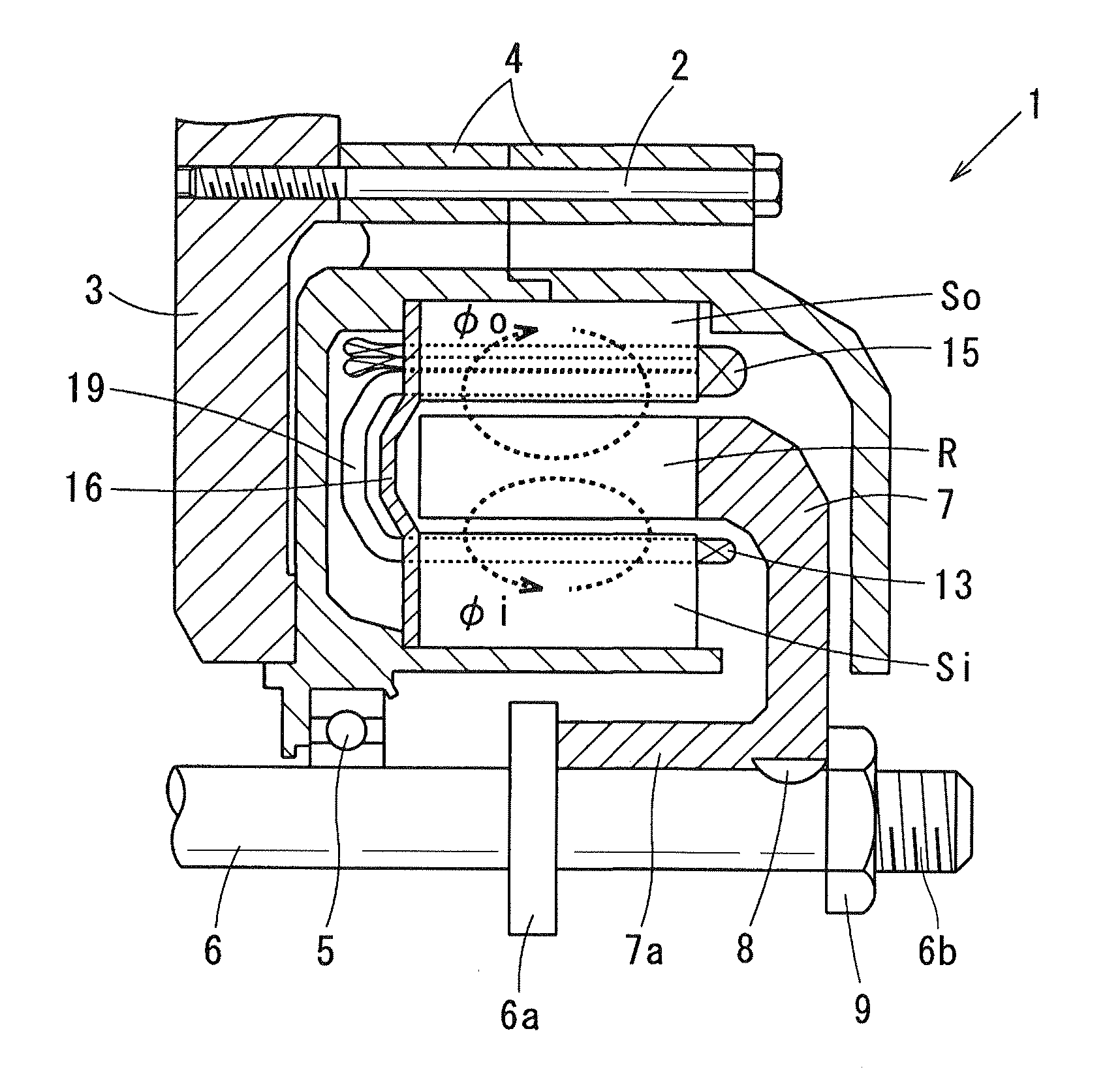
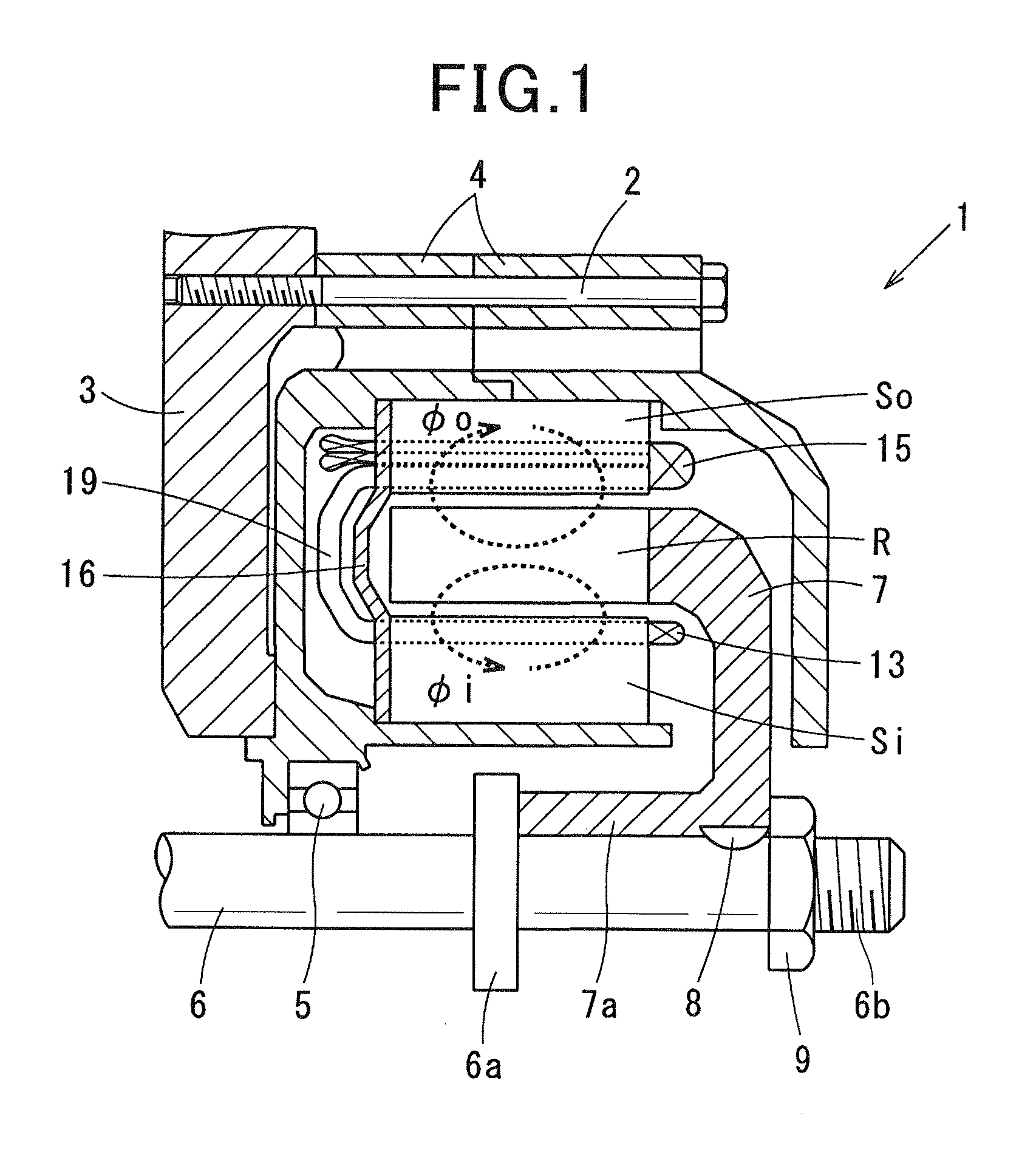
[0057]Referring to FIG. 1 to FIG. 3, (a) and (b) of FIG. 4, a first embodiment of the present invention is described. FIG. 1 is a general schematic diagram illustrating a double-stator motor 1 according to the first embodiment. As shown in FIG. 1, the double-stator motor 1 includes a housing 3, a motor case 4, a shaft 6, an annular rotor R, an inner stator Si and an outer stator So. The motor case 4 is fixed to the housing 3 via a through bolt 2. The shaft 6 is rotatably supported by the motor case 4 via a bearing 5. The annular rotor R is connected to the shaft 6 via a rotor disc 7. The inner stator Si is arranged on a radially inner side of the rotor R and fixed to the motor case 4. The outer stator So is arranged on a radially outer side of the rotor R and fixed to the motor case 4. The rotor disc 7 is made such as of non-magnetic SUS (special use stainless steel). The rotor disc 7 includes a cylindrically shaped boss 7a at a radially center thereof. The boss 7a is fitted to the ...

second embodiment

[0078]Referring now to FIG. 11, (a) and (b) of FIG. 12, hereinafter is described a second embodiment of the present invention. In the second and the subsequent embodiments, the components identical with or similar to those in the first embodiment are given the same reference numerals for the sake of omitting unnecessary explanation. FIG. 11 is a partial cross-sectional view illustrating the rotor R, and the inner and outer stators Si and So. (a) of FIG. 12 is a diagram illustrating the shapes of the inner and outer stator windings 13 and 15 as viewed from the axial direction. (b) of FIG. 12 is a side view illustrating the shapes of the inner and outer stator windings 13 and 15. Similar to the first embodiment, flat conductors are used as the inner and outer stator windings 13 and 15. The flat conductors both have a rectangular cross section perpendicular to the longitudinal direction, and have the same cross-sectional area perpendicular to the longitudinal direction. In the first em...

third embodiment

[0080]Referring to FIG. 13, (a) and (b) of FIG. 14, hereinafter is described a third embodiment of the present invention. FIG. 13, (a) and (b) of FIG. 14 correspond to FIG. 11, (a) and (b) of FIG. 12 of the second embodiment, respectively. In the third embodiment, as shown in FIG. 13, the conductors of the inner and outer stator windings 13 and 15 all have the same cross-sectional shape (substantially square) perpendicular to the longitudinal direction, and the same cross-sectional area perpendicular to the longitudinal direction. In FIG. 13 illustrating a partial cross-sectional view of the rotor R, and the inner and outer stators Si and So, hatching indicating cross section is omitted. As shown in (a) and (b) of FIG. 14, no twist is given to the bridges 19 connecting between the respective inner in-slot conductors 15a1 of the outer stator winding 15 and the respective in-slot conductors 13a of the inner stator winding 13. The above configuration is suitable for a motor having the ...


PUM


Abstract

A double-stator motor of an example embodiment includes: an annular rotor connected to a rotary shaft and integrally rotates with the rotary shaft, an inner stator arranged radially inward of the rotor, and an outer stator arranged radially outward of the rotor. The rotor includes a plurality of segments annularly arranged in the circumferential direction, spaced apart from each other by a predetermined distance, and a plurality of permanent magnets each interposed between circumferentially adjacent segments, the permanent magnets being alternately magnetized in the circumferentially opposite direction. The rotor, the inner stator and the outer stator have the same number of poles. The inner and outer stator windings of the inner and outer stators, respectively, are connected so that their phases are reversed to each other. Thus, the magnetic fields generated by the magnetomotive forces of the inner and outer stators are applied to specific segments in parallel.

Description

CROSS-REFERENCE TO RELATED APPLICATION[0001]This application is based on and claims the benefit of priority from earlier Japanese Patent Application No. 2011-231635 filed Oct. 21, 2011, the description of which is incorporated herein by reference.BACKGROUND OF THE INVENTION[0002]1. Technical Field of the Invention[0003]The present invention relates to the structure of a motor that can employ magnets, such as ferrite magnets, having a tendency of demagnetization, and in particular to a double-stator motor that includes an annular rotor in which circumferentially magnetized permanent magnets are individually sandwiched between segment poles, and inner and outer three-phase stators which are arranged radially inside and outside, respectively, of the rotor.[0004]2. Related Art[0005]Mainstream motors in recent years are synchronous motors embedding neodymium magnets as permanent magnets. For such neodymium magnets, a heavy rare earth metal, such as dysprosium, is indispensable as an addi...

Claims


Application Information

Patent Timeline
IPC IPC(8): H02K16/04H02K3/28
CPCH02K3/28H02K16/04H02K1/2786H02K21/22H02K1/276H02K21/14H02K1/2791H02K3/50H02K23/36H02K3/505H02K3/52H02K3/522H02K3/521H02K23/38
Inventor KUSASE, SHIN
Owner DENSO CORP
Why Eureka
Try Eureka