Culvert with a deformation zone

a culvert and deformation technology, applied in the field of civil engineering, can solve the problems of long construction time, inability to allow construction works, and identical seriousness, and achieve the effects of short construction time, easy maintenance, and reduced overload valu

Inactive Publication Date: 2013-04-25
NOVOTNY PETR
View PDF8 Cites 4 Cited by
  • Summary
  • Abstract
  • Description
  • Claims
  • Application Information

AI Technical Summary

Benefits of technology

[0020]It is furthermore advantageous that the front component in the vertical direction exceeds in height the upper edges of the bed shoulders over the upper edges of the lateral rigid girders or over the upper edges of the strips. In this embodiment, the front component sweeps the flexible strips during the impact to avoid their contact with a car crashed and forms a border for application of the backfilling or bitumen or other road surface of the driveway.
[0021]It is furthermore advantageous when the front component forms a sandwich panel with alternate soft polyurethane layers, air layers and fixed layers made of solid plastic ribs for spatial rigidity in two directions, whereas the road-fence and / or warning column is preferably anchored to the front component.
[0022]It is finally advantageous when draining holes are made on the bed shoulders for draining water from side walls of the ditch in the culvert.
[0023]The advantages of the culvert according to the invention consist in that the double deformation zone significantly reduces the overload value applicable on the car crew at the moment of impact and in consequence of which traumatic injuries occur. Thanks to simple composition of the prefabricated components, the culvert is characteristic by a short construction time, for a standard culvert the construction time is about 2 days. Another benefit is an easy maintenance because the culvert has higher bore diameter compared to classic construction procedure; if the culvert is highly contaminated (e.g. by sludge), the culvert can be disassembled easily and reassembled after cleaning and when the culvert is damaged by an impact, only damaged part need be replaced.
[0024]Furthermore, the culvert is characteristic by high durability due to improved quality of prefabricated components and lower price due to series production of the prefabricated components as well as easy construction without use of heavy machinery.
[0025]Finally, better draining is advantageous because the culvert does not interrupt draining of the ground plane and improves better road draining along the culver in case of rubber road surface.

Problems solved by technology

The main disadvantage of this solution, particularly with respect to safety, is the vertical front of the culvert because consequences of frontal crash of a car slipping from the road hitting the vertical culvert front are usually serious and result in fatal car accidents.
The other disadvantage is the wet process of construction of the fronts lengthening the construction time and does not allow construction works at low temperatures.
On the other hand it happens that the car rides on the culvert at high speed and is catapulted back to the road with identically serious, if not much more serious, consequences than the frontal crash with the vertical culvert front.
In addition, construction of the inclined front is technologically much more demanding and appropriate cutting of the tube is required and therefore, construction of the culvert is more expensive and time demanding compared to the vertical front culvert, including the disadvantage of the wet process.
Serious consequences of the frontal impact are thus really minimized but on the other hand, construction, building and maintenance of the culvert is demanding.
The solution is extensive and heavy, which increases both production as well as transport costs related to prefabricated components.
This solution is not suitable for driveways of cars because of limited loading capacity.

Method used


Image

  • Culvert with a deformation zone
  • Culvert with a deformation zone
  • Culvert with a deformation zone

Examples


Embodiment Construction

[0032]The below described and depicted particular examples of the invention embodiments are considered illustrative and they in no way limit the invention embodiment to the examples herein presented. Professionals in the technology sphere will find or will be able to find more or fewer equivalents to the specific embodiments of the invention herein described in their routine experimental work. These equivalents will also be included in the following claims.

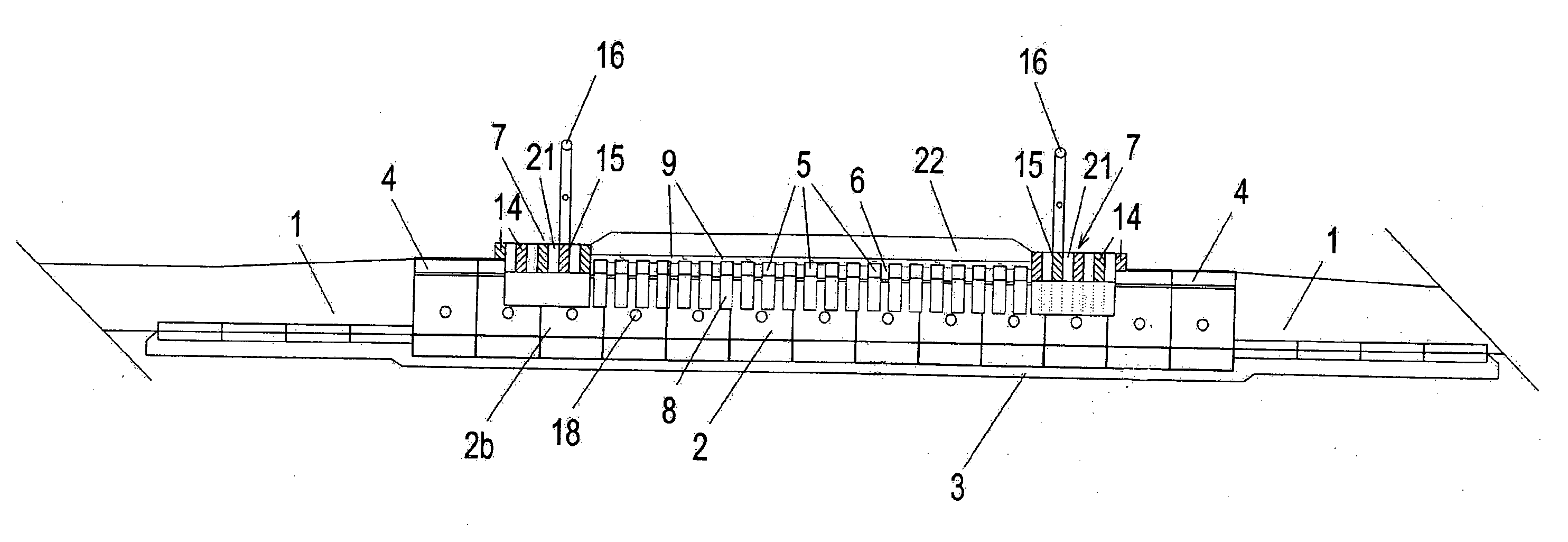
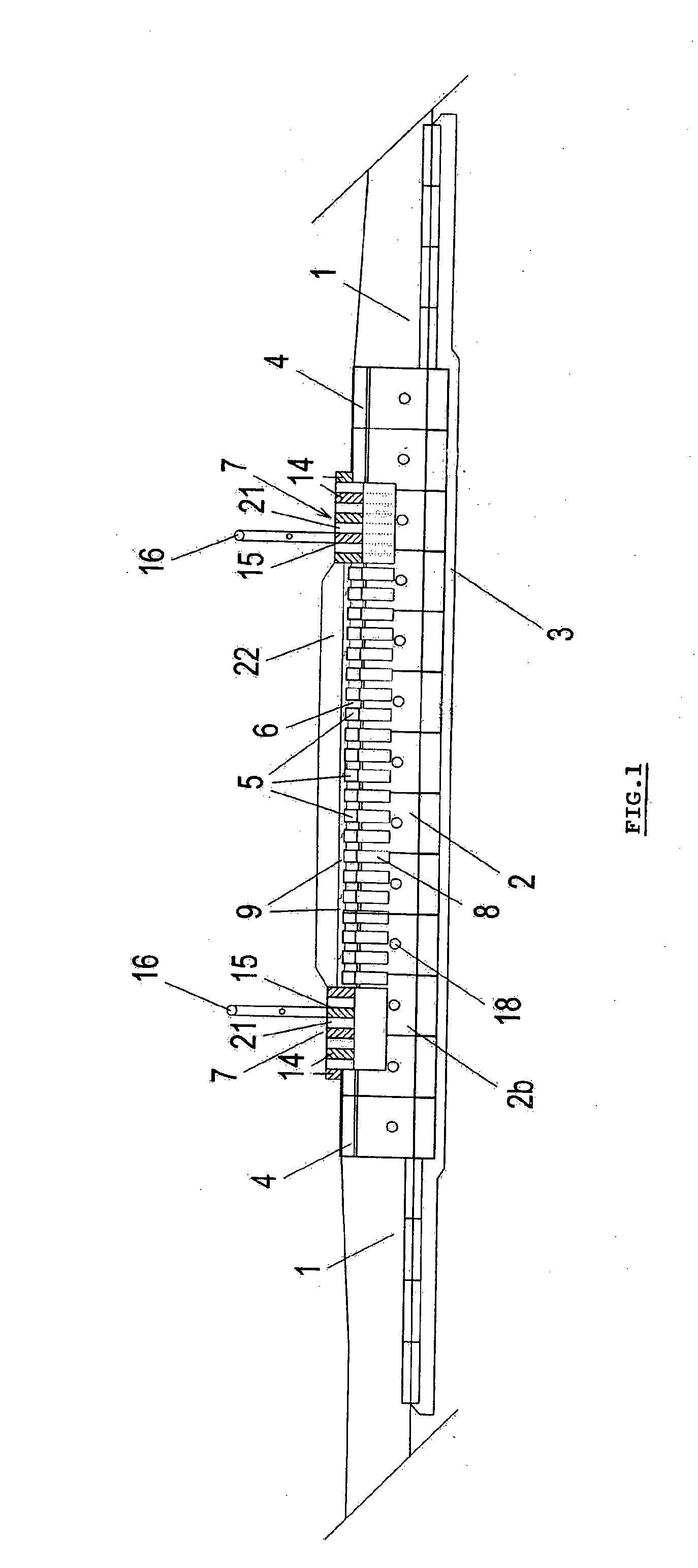
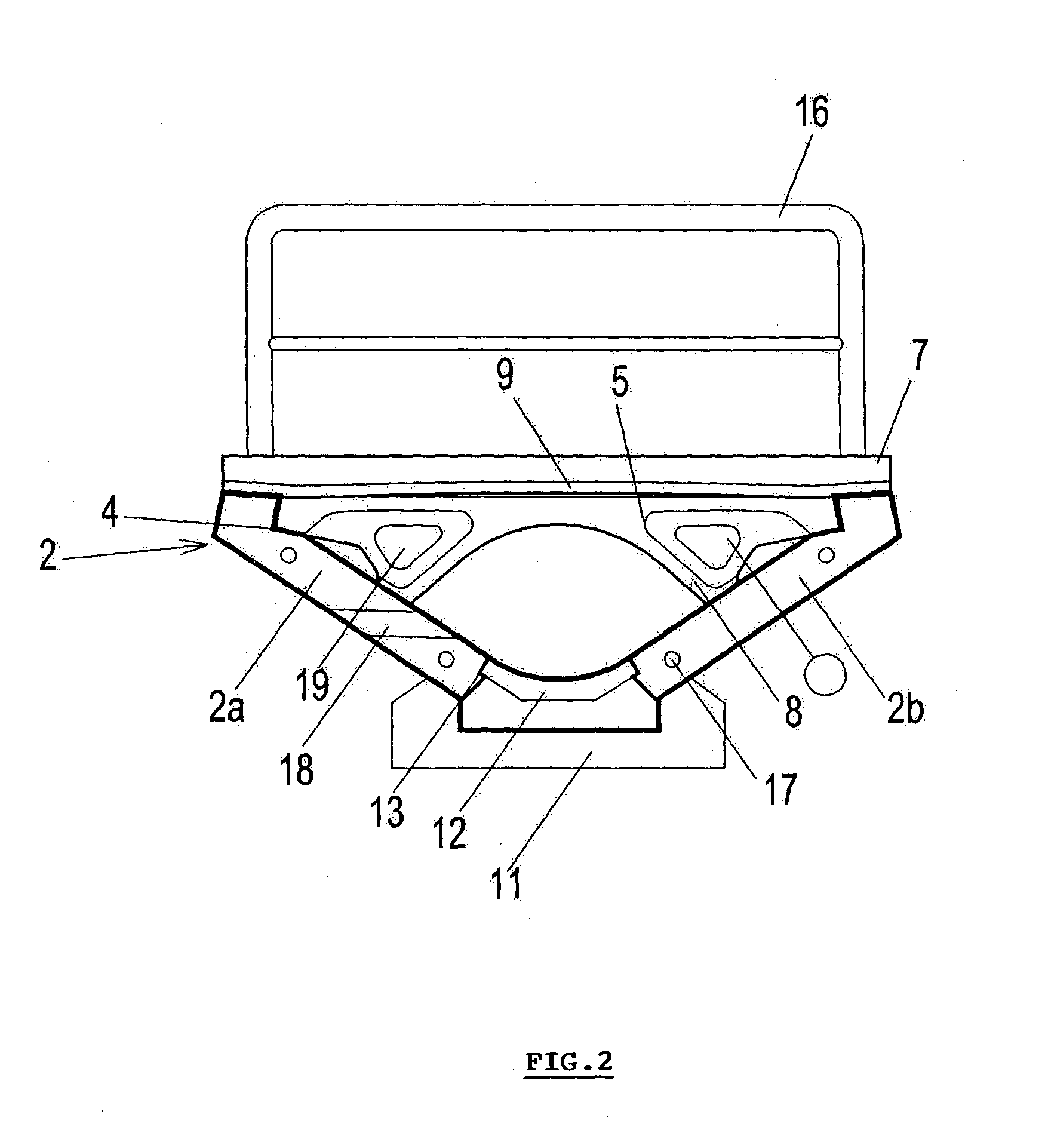
[0033]The specific culvert design is always derived from the required utility length of the culvert, span of the bridged road ditch 1, transport load of the culvert, speed, intensity and composition of the traffic flow on adjacent road. For the culvert according to the design example, FIG. 1, FIG. 2, FIG. 3, the road ditch 1 bottom has a plain concrete foundation 3 made of plain concrete. The foundation 3 can be directly fitted with the integrated prefabricated beds 2 in the “V” shape as shown on FIG. 1 and FIG. 5 or the beds 2 ca...


PUM


Abstract

The culvert with the deformation zone consists of prefabricated components arranged in the road ditch (1). The culvert includes at least one fixed basic component and at least one deformation component sliding in the basic component in the direction of the longitudinal ditch axis (1) and covered by a deformable decking or also by backfilling or other cover. The substance of the invention lies in the fact the basic component consists of a set of prefabricated concrete or reinforced concrete beds (2) formed in “V”-shape and placed one after another on the concrete base (3) in the road ditch (1) so that the shoulders (2a, 2b) of the beds (2) abut the ditch walls (1). Both shoulders (2a, 2b) of each bed (2) are fitted with opposite guiding recess (4) in the upper part for placement of deformation components formed by a set of at least two lateral rigid girders (5) installed with the possibility of the sliding movement in the direction of the longitudinal ditch axis (1). There are deformation gaps (6) between each lateral girder (5) and at least one front of the culvert contains at least one further deformation component in the recesses (4) with possibility of sliding movement that forms the front component (7) fitted with soft layer (14) from soft and resilient deformable material on at least its front part.

Description

BACKGROUND AND SUMMARY OF THE INVENTION[0001]This invention relates to civil engineering, in particular to a culvert built as a crossing or driveway especially in the road ditches that drain water from roads. The subject of the invention is a culvert of increased safety fitted with deformation zone that limits the risk of fatal consequences of accidents when a car goes off the road and hits the culvert.[0002]In most cases, the culverts are constructed as solid structures with vertical fronts. A tube for conducting water through the culvert is installed in a concrete bed and concreted and backfilled between solid, usually concrete or bricked, fronts. The main disadvantage of this solution, particularly with respect to safety, is the vertical front of the culvert because consequences of frontal crash of a car slipping from the road hitting the vertical culvert front are usually serious and result in fatal car accidents. The other disadvantage is the wet process of construction of the ...

Claims


Application Information

Patent Timeline
Patent Type & Authority Applications(United States)
IPC IPC(8): E01F5/00
CPCE01F5/005
Inventor NOVOTNY, PETR
Owner NOVOTNY PETR
Why Eureka
Try Eureka