
Clock Synchronization in Shared Baseband Deployments

a technology of baseband and clock synchronization, applied in the direction of synchronisation signal speed/phase control, digital transmission, electrical equipment, etc., can solve the problems of high drop-off rate, impaired data services, and synchronization issues that are further dilapidating

Active Publication Date: 2013-05-02
TELEFON AB LM ERICSSON (PUBL)
View PDF3 Cites 8 Cited by
  • Summary
  • Abstract
  • Description
  • Claims
  • Application Information

AI Technical Summary

Benefits of technology

The present invention provides a method and system for synchronizing timing between two systems operating with a multi-standard radio. This is achieved by recovering a clock from one system's output and using it to regenerate a synchronization source for the other system. This allows for consistent timing between the two networks even in the case of lost input synchronization sources or drifting timing sources. The technical effect of the invention is improved synchronization between systems and better timing consistency between networks.

Problems solved by technology

Emerging deployments of shared radio solutions for base stations operating on multiple standards face particular challenges in relation to operating on a common clock synchronization.
If individual base stations drift outside the specified frequencies, mobile handoff performance decays, calls interfere, and calls cannot be made, resulting in high dropped-call rates and impaired data services.
These synchronization issues are further dilapidating in shared baseband deployments since holdover requirements are not standard; they vary depending on the system type, complexity, and operator's requirements.
Existing clock synchronization solutions provide limited holdover capabilities in the case where one or both of the systems lose their synchronization inputs, leading to the outputs becoming unsynchronized with each other.
For these reasons, traditional synchronization has limited capabilities in situations as described above.

Method used


Image

  • Clock Synchronization in Shared Baseband Deployments
  • Clock Synchronization in Shared Baseband Deployments
  • Clock Synchronization in Shared Baseband Deployments

Examples


Embodiment Construction

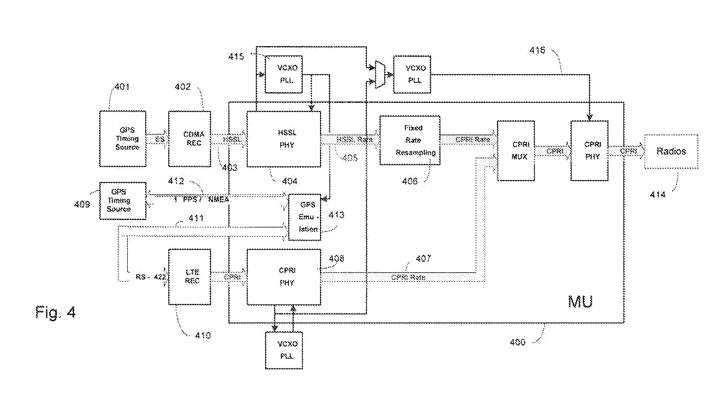
[0015]In order to lighten the following description, the following acronyms will be used:[0016]1 PPS One Pulse per second[0017]BTS Base Station[0018]CBTS CDMA Base Station[0019]LTE REC Digital Radio Unit LTE[0020]GPS Global Positioning System[0021]HSSL High Speed Serial Link[0022]OCXO Oven Controlled Crystal Oscillator[0023]PHY Physical Interface[0024]VCXO Voltage Controlled Crystal Oscillator[0025]MU Multiplexer Unit

[0026]As indicated above, the present invention addresses the issues brought out by the aforementioned prior art.

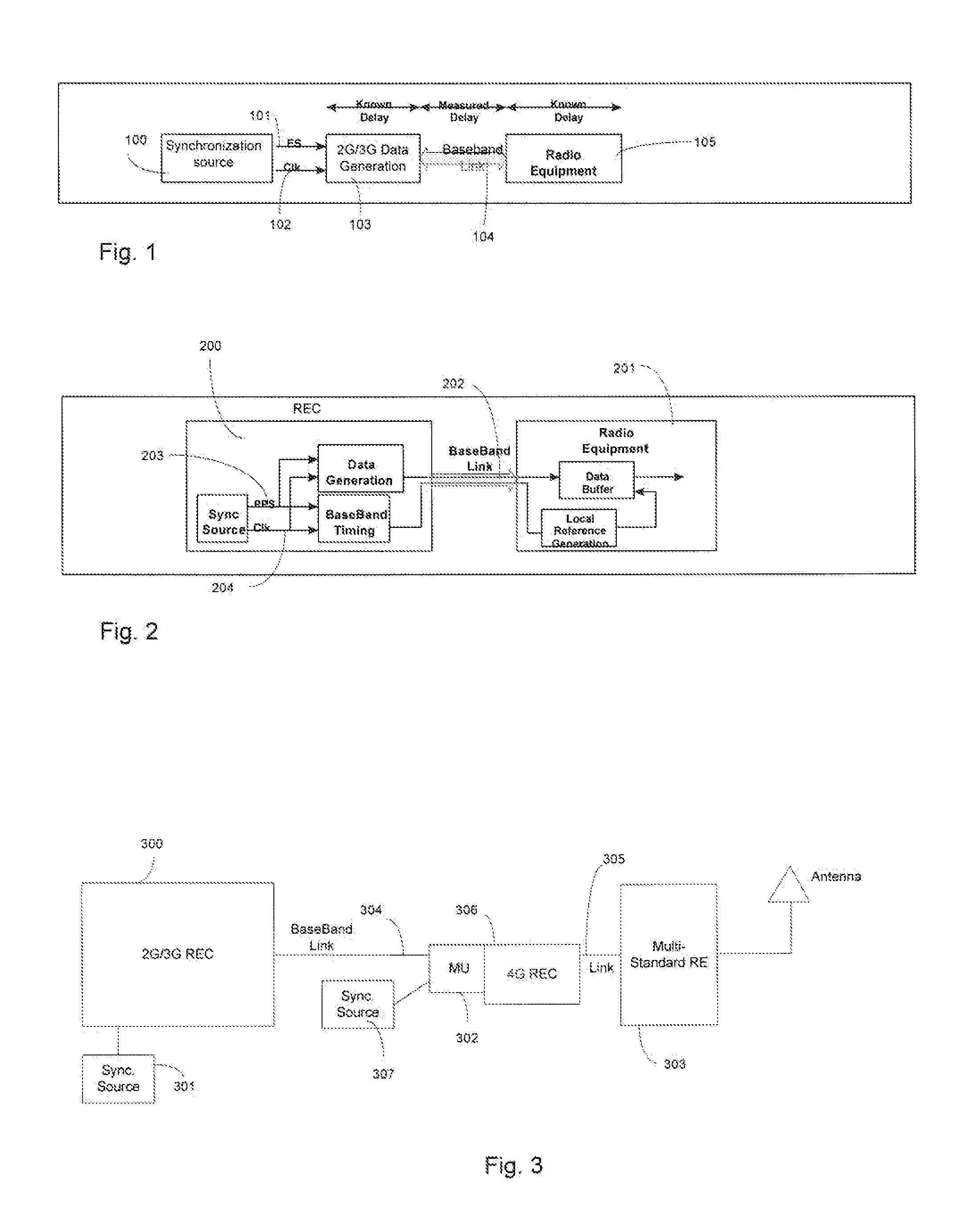
[0027]With reference to FIG. 1, we have shown a block diagram illustrating the timing principles of a 2G / 3G radio. A timing source 100, such as GPS signal creates an ES (even second) mark 101 synchronized to GPS time, along with an associated (phase-locked) clock 102. It provides these signals to the 2G / 3G Data generation equipment 103, which uses them to generate the required codes with an advance with respect to this mark. The amount of this advance is dete...


PUM


Abstract

A method and an interface unit is provided to maintain timing synchronization between a first Radio Equipment Controller (REC) and a second REC operating with a multi-standard base station. The first REC receives a synchronization signal and synchronized data output is generated from the synchronization signal. A clock signal is then generated from the synchronized data output. At the second REC, the synchronized data output is received and a synchronization source is then reconstructed from the first clock signal. A timing and frequency component of a second clock signal is then aligned to that of the reconstructed synchronization source, such that the second REC can maintain synchronization with the first REC.

Description

FIELD OF THE INVENTION[0001]The present application relates generally to clock synchronization and, more specifically, to clock synchronization in shared baseband deployments.BACKGROUND OF THE INVENTION[0002]Network operators upgrading their networks from 2G / 3G networks to 4G networks; want a network evolution solution which permits the leveraging of a portion of their installed baseband equipment. In some cases this means that multi-standard mixed mode radios are used to support efficient in-band combining to ease the service transition from 2G / 3G equipment to 4G equipment. Emerging deployments of shared radio solutions for base stations operating on multiple standards face particular challenges in relation to operating on a common clock synchronization. Each standard usually run from its own clocking domain.[0003]When the timing or synchronization reference is temporarily lost, a network's ability to maintain time and sync stability becomes critical to ensure continued optimal net...

Claims


Application Information

Patent Timeline
IPC IPC(8): H04L7/04
CPCH04J3/0688
Inventor PRZADA, JAROSLAWREMPEL, GLENHUISMAN, KEN
Owner TELEFON AB LM ERICSSON (PUBL)
Learn More