
Wind or tidal turbine blade having an attachment

a technology of wind or tide turbine blade and attachment, which is applied in the direction of machines/engines, renewable energy generation, greenhouse gas reduction, etc., can solve problems such as transportation difficulties, and achieve the effect of convenient lamina

Inactive Publication Date: 2013-05-02
GURIT (UK) LTD
View PDF8 Cites 17 Cited by
  • Summary
  • Abstract
  • Description
  • Claims
  • Application Information

AI Technical Summary

Benefits of technology

The present invention provides a way to make a threaded metal insert into a blade root that is lighter and easier to work with than existing systems, but also easier to laminate.

Problems solved by technology

Wind turbine blades are being manufactured in increasing length, for example up to about 60 m at the present time, which causes difficulty in transportation.

Method used


Image

  • Wind or tidal turbine blade having an attachment
  • Wind or tidal turbine blade having an attachment
  • Wind or tidal turbine blade having an attachment

Examples


Embodiment Construction

[0069]Although the illustrated embodiments relate to wind turbine blades, it will be apparent to a skilled person how to adapt the present invention to manufacture tidal turbine blade embodiments.

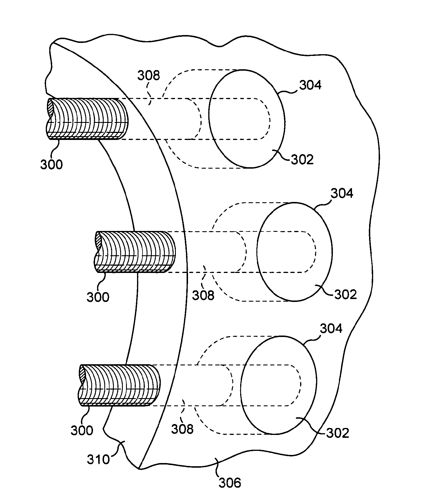
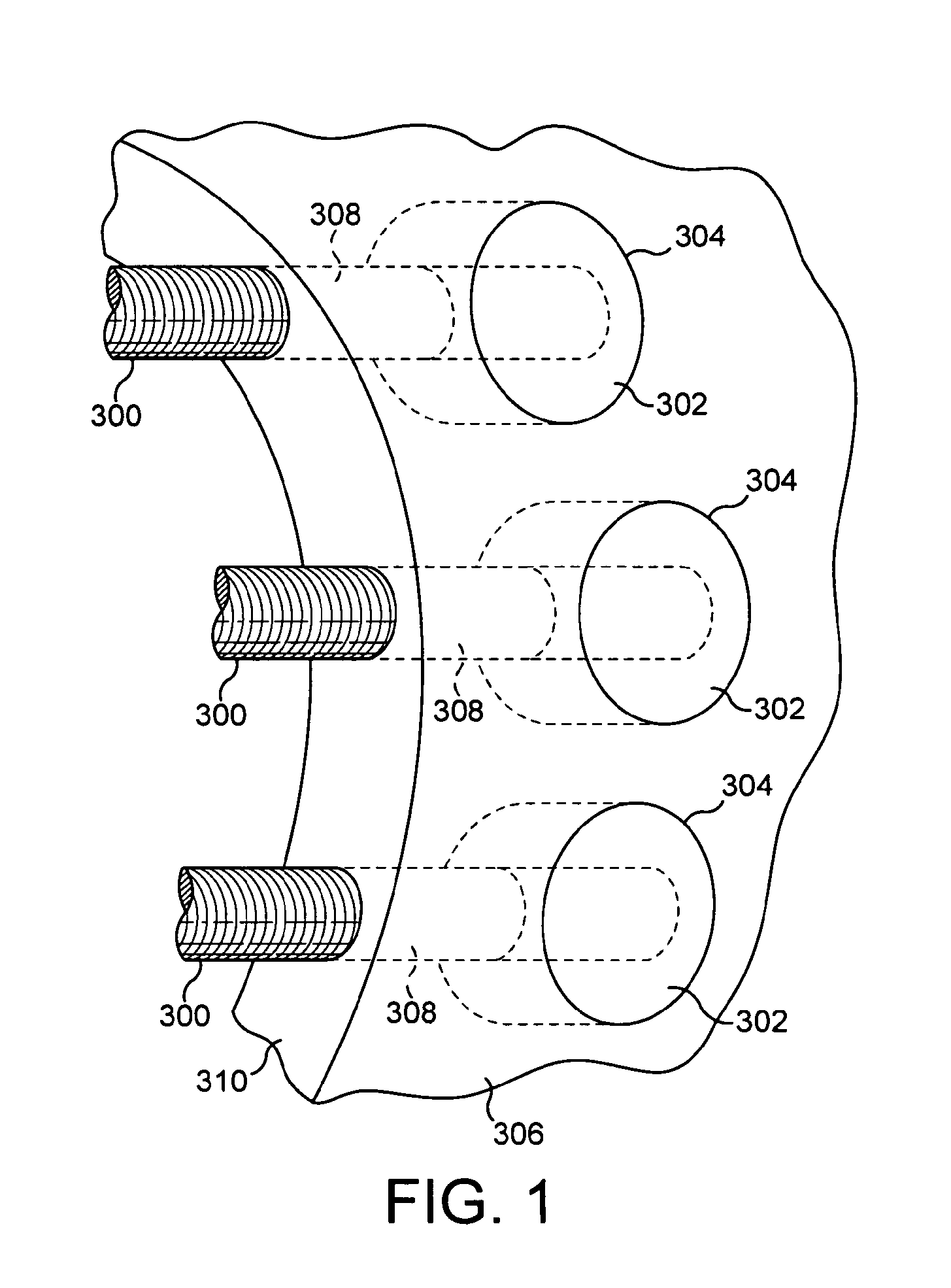
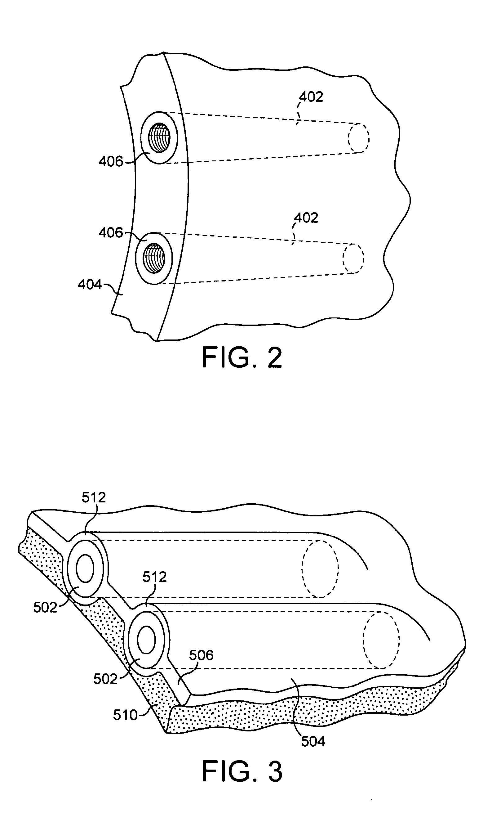
[0070]Referring to FIGS. 4 to 6, there is shown a wind turbine blade root attachment 2 in accordance with a first embodiment of the present invention. The root 4 of the wind turbine blade 6 is composed of a laminate 8 of a fibre reinforced composite material, optionally with a core material therein, forming an annular, most typically cylindrically annular, root structure for attachment to the hub (not shown) by the root attachment 2. The root attachment 2 comprises at least one bolt support comprising an insert 10, shown in greater detail in FIG. 5, which has a rearwardly directed face 12 mating with an end face 14 of the annular root 4. In the illustrated embodiment the rearwardly directed face 12 is planar and the end face 14 is correspondingly planar.

[0071]No holes are drilled in the end...


PUM


Abstract

A wind or tidal turbine blade having an attachment, the attachment including: a support portion of the turbine blade, the support portion having opposite surfaces; an insert adapted to mount a bolt for attaching the support portion to another structure; and a mounting for fitting the insert to the support portion, the mounting including a layer extending over a front face of the insert and bonded to the opposite surfaces of the support portion on opposite sides of the insert, the layer permitting passage of a bolt therethrough to or from the insert.

Description

FIELD OF THE INVENTION[0001]The present invention relates to a wind or tidal turbine blade having an attachment, in particular a root attachment for attaching the root of the blade to a hub or an attachment for attaching together two portions of a wind or tidal turbine blade.BACKGROUND[0002]A wind turbine generator is typically made of these parts: a tower; a nacelle sitting at the top of the tower including generators, gearboxes or any means to convert wind energy to electrical energy; a hub with a pitch bearing for each blade; and a plurality, e.g. two or three, of wind turbine blades each fitted to a respective pitch bearing of the hub. A tidal generator correspondingly includes a hub and blades fitted thereto.[0003]The “root” of the blade is the end attached to the hub via the pitch bearing and is typically cylindrically annular, and shaped and dimensioned to mate with the bearing. Blades are commonly built using composite materials, in particular fibre reinforced composite mate...

Claims


Application Information

Patent Timeline
Patent Type & Authority Applications(United States)
IPC IPC(8): F03D11/00
CPCF03B3/121F03D1/0658F03D11/00Y02E10/223Y02E10/721F05B2260/301F05B2240/302F03D80/00Y02E10/74Y02E10/728Y02E10/20Y02E10/72F03D80/70F03D7/022F03D1/065F03D1/0691F03D3/064F03D13/20
Inventor MCEWEN, LUKE NEILLOUARN, FREDERIC HERVESELLIER, JULIENCHIGNELL, ANTHONY JAMES
Owner GURIT (UK) LTD
Learn More