Stamped feature for visual pattern recognition

a technology of stamped features and pattern recognition, which is applied in the direction of manufacturing tools, transportation and packaging, and other domestic objects, can solve the problems of defective wire bonding, inconsistent or jagged interface between plastic and lead frame edges, and assembly line stoppages

Inactive Publication Date: 2013-05-02
ILLINOIS TOOL WORKS INC
View PDF12 Cites 0 Cited by
  • Summary
  • Abstract
  • Description
  • Claims
  • Application Information

AI Technical Summary

Benefits of technology

[0007]To produce a consistently clean edge for pattern recognition, a feature in the mold is used to keep plastic away from the edge used for pattern recognition. Rather than keeping the plastic away from the outside edge of the stamping, it is preferable to establish an opening in the stamping inwardly from the outside edge. A pin from the mold can be placed into the hole to keep the molten plastic out of the hole during the molding process.

Problems solved by technology

Inconsistency in the visual quality of the pattern recognition features can lead to misplacing wire bonds, which thereafter can result in assembly-line stoppages.
If, during the molding process, the plastic flows up to and over the top edge of the insert molded lead frame, the interface between plastic and the lead frame edge can be inconsistent or jagged.
A jagged, inconsistent edge creates recognition difficulties for the pattern recognition system and can result in defective wire bonds.

Method used


Image

  • Stamped feature for visual pattern recognition
  • Stamped feature for visual pattern recognition
  • Stamped feature for visual pattern recognition

Examples


Embodiment Construction

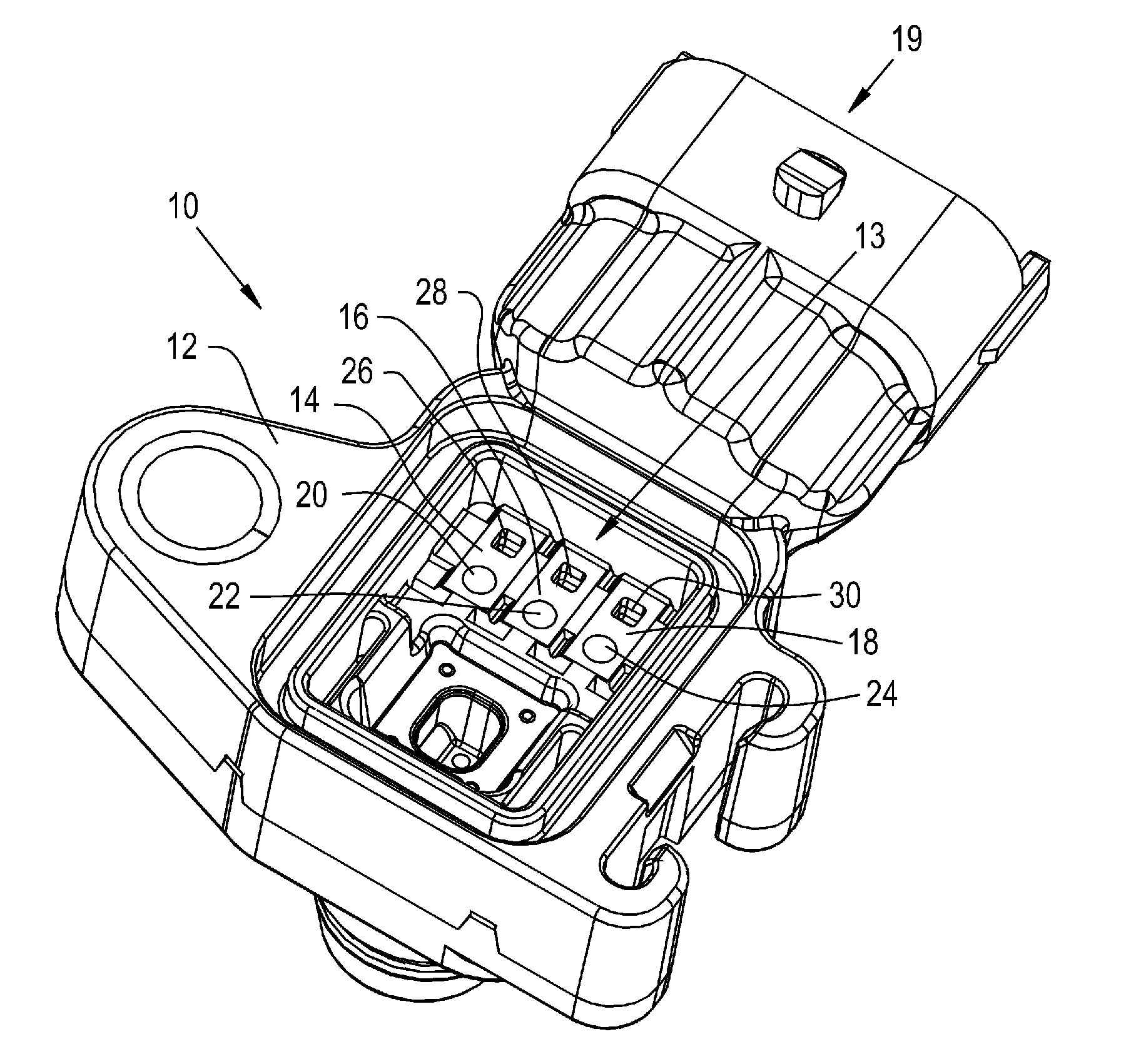
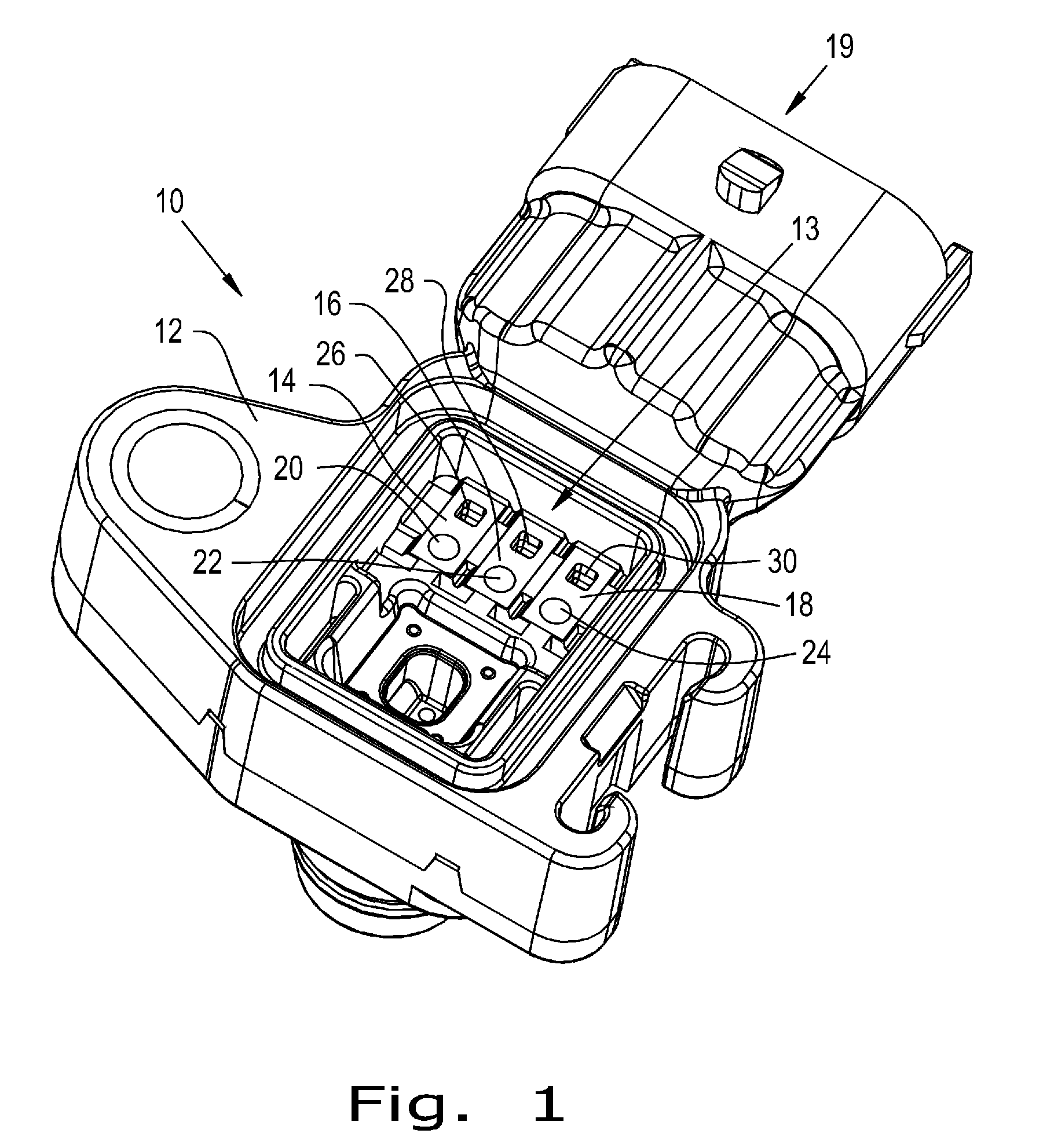
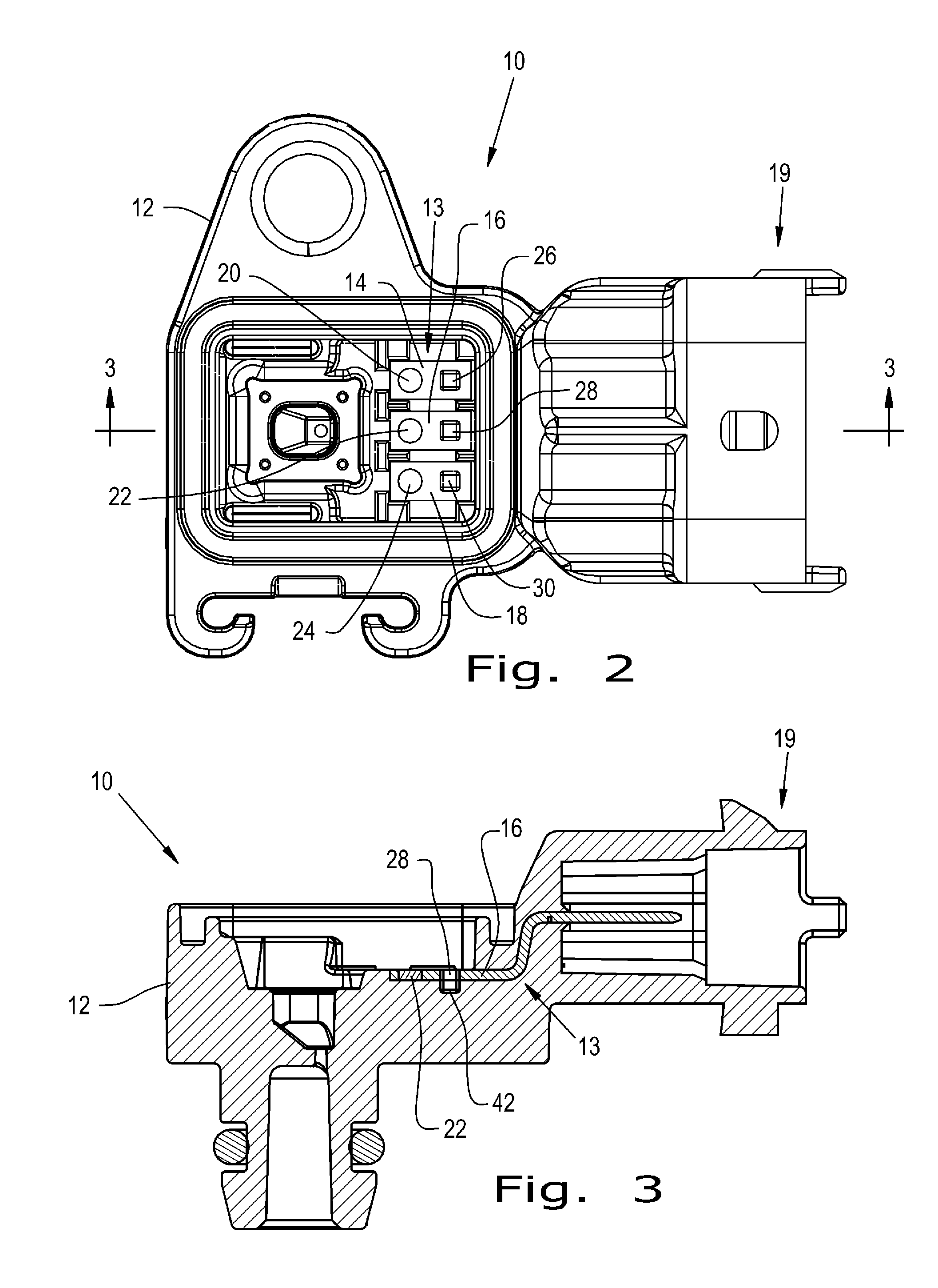
[0017]Referring now more specifically to the drawings and to FIG. 1 in particular, an insert molded electrical component 10 is shown. Component 10 has a molded plastic body 12 with an insert molded lead frame 13 including electrically conductive bodies 14, 16, 18 configured for connecting by physical attachment to another component in a connector end 19 of component 10. Each of the conductive bodies 14, 16, 18 includes a wire bonding site, such as a bond pad 20, 22, 24, respectively, for wire bonding in a subsequent assembly operation. As known to those skilled in the art, wires or conductors of other types are electrically connected to bond pads 20, 22&24 to establish an electrical connection between electrically conductive bodies 14, 16, 18 and another part or component (not shown). An automated wire bonder is used to electrically connect wires or conductors to bond pads 20, 22, 24, the wire bonder including a pattern recognition system and software for determining where the elect...


PUM

PropertyMeasurementUnit
sizeaaaaaaaaaa
conductiveaaaaaaaaaa
electricalaaaaaaaaaa

Abstract

A lead frame for insert molding in a plastic body is provided with an opening defining an edge suitable for detection by pattern recognition systems. During the insert molding process, a pin is positioned in the opening so that the opening remains void of plastic following the injection molding process.

Description

CROSS-REFERENCE TO RELATED APPLICATIONS[0001]The present application claims the benefits of U.S. Provisional Application Ser. No. 61 / 551,747 filed Oct. 26, 2011.FIELD OF THE INVENTION[0002]The present invention relates generally to plastic molding processes, and more particularly, to injection molding processes that incorporate insert molding a stamped lead frame or other metal conductor to which electrical connections subsequently are made using automated processes employing pattern recognition software for locating the electrical connection site.BACKGROUND OF THE INVENTION[0003]In the automotive electronics packaging industry, wire bonding is used as a means for making electrical connections between electronic components and a stamped lead frame that often is insert molded within an injection molded plastic housing. A wire is bonded with specialized equipment, known as a wire bonder, to the electronic component and to the stamped lead frame. The wire bonder uses a pattern recogniz...

Claims


Application Information

Patent Timeline
Patent Type & Authority Applications(United States)
IPC IPC(8): B29C39/10B32B3/10B23P17/00
CPCH01R43/24B29L2031/36Y10T428/24298Y10T29/4998Y10T428/24331B29C45/14655B29C45/14065B29C2045/14147B29L2031/3493
Inventor SMITH, RONALD M.
Owner ILLINOIS TOOL WORKS INC
Why Eureka
Try Eureka