Chimney

Inactive Publication Date: 2013-05-02
ZHENG DEMING
View PDF3 Cites 1 Cited by
  • Summary
  • Abstract
  • Description
  • Claims
  • Application Information

AI Technical Summary

Benefits of technology

[0014]Advantages of the invention are summarized below: first of all, the baffle arranged on one side wall of the smoke inlet is conducive to forming the eddy flow of the smoke, lower the resistance from the chimney, and improve the capabili

Problems solved by technology

However, this structure has a large resistance and a poor particulate collecting capability.
Furthermore, smoke flows upwards along th

Method used


Image

  • Chimney
  • Chimney
  • Chimney

Examples


Example

EXAMPLE 1

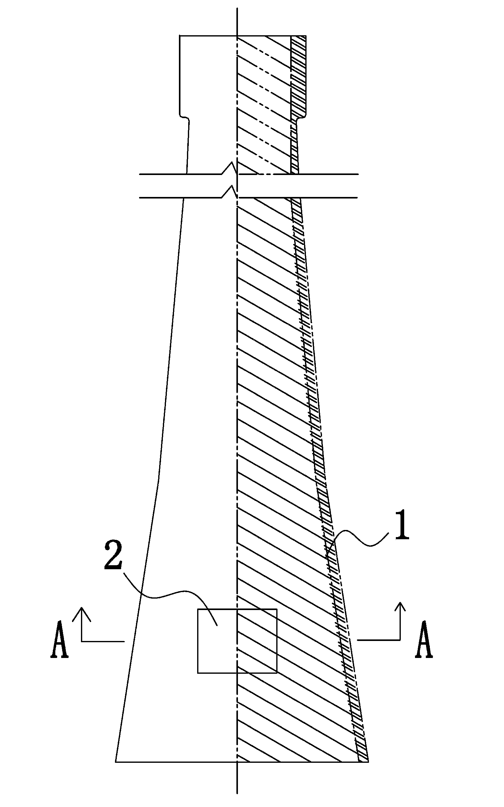
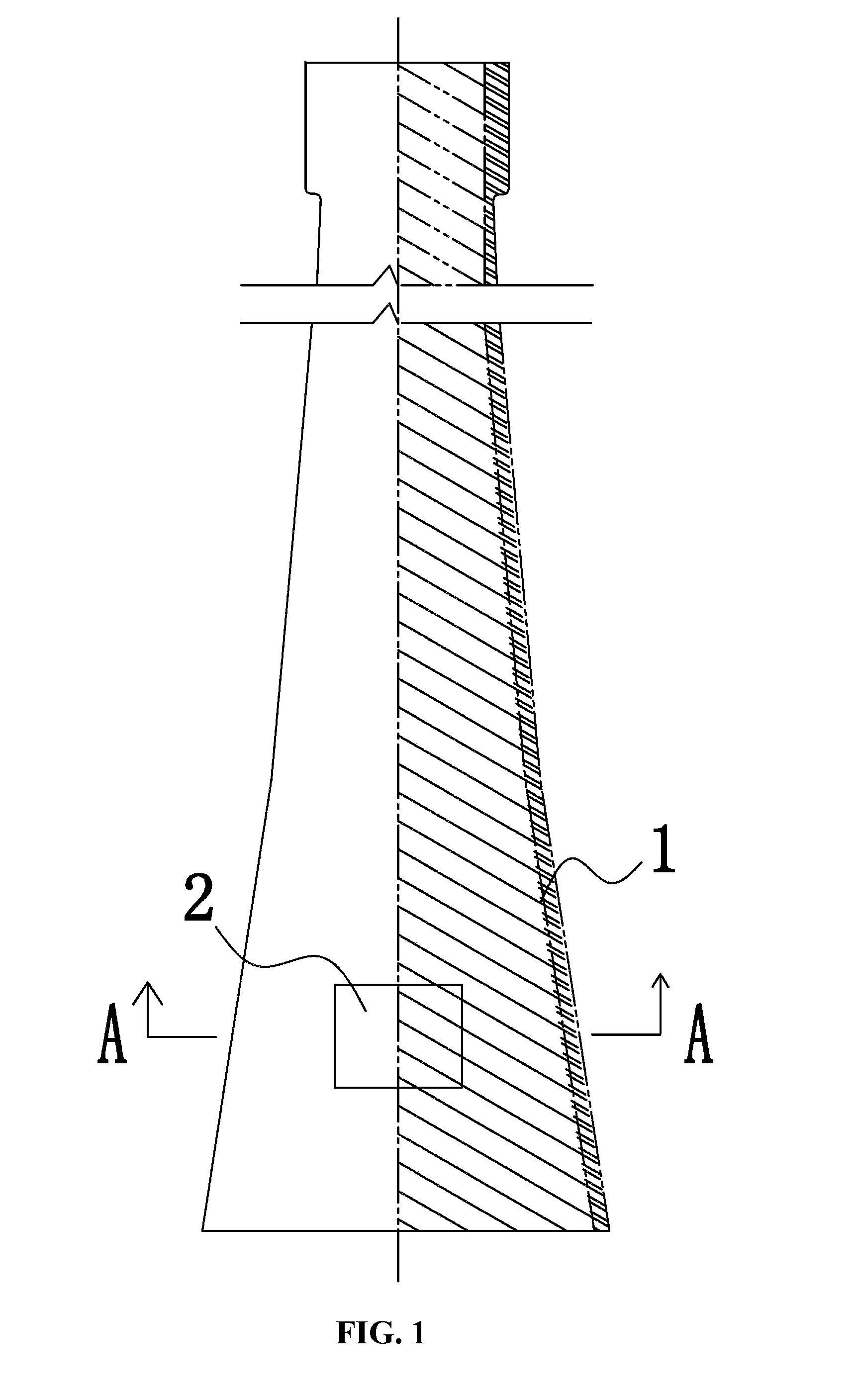
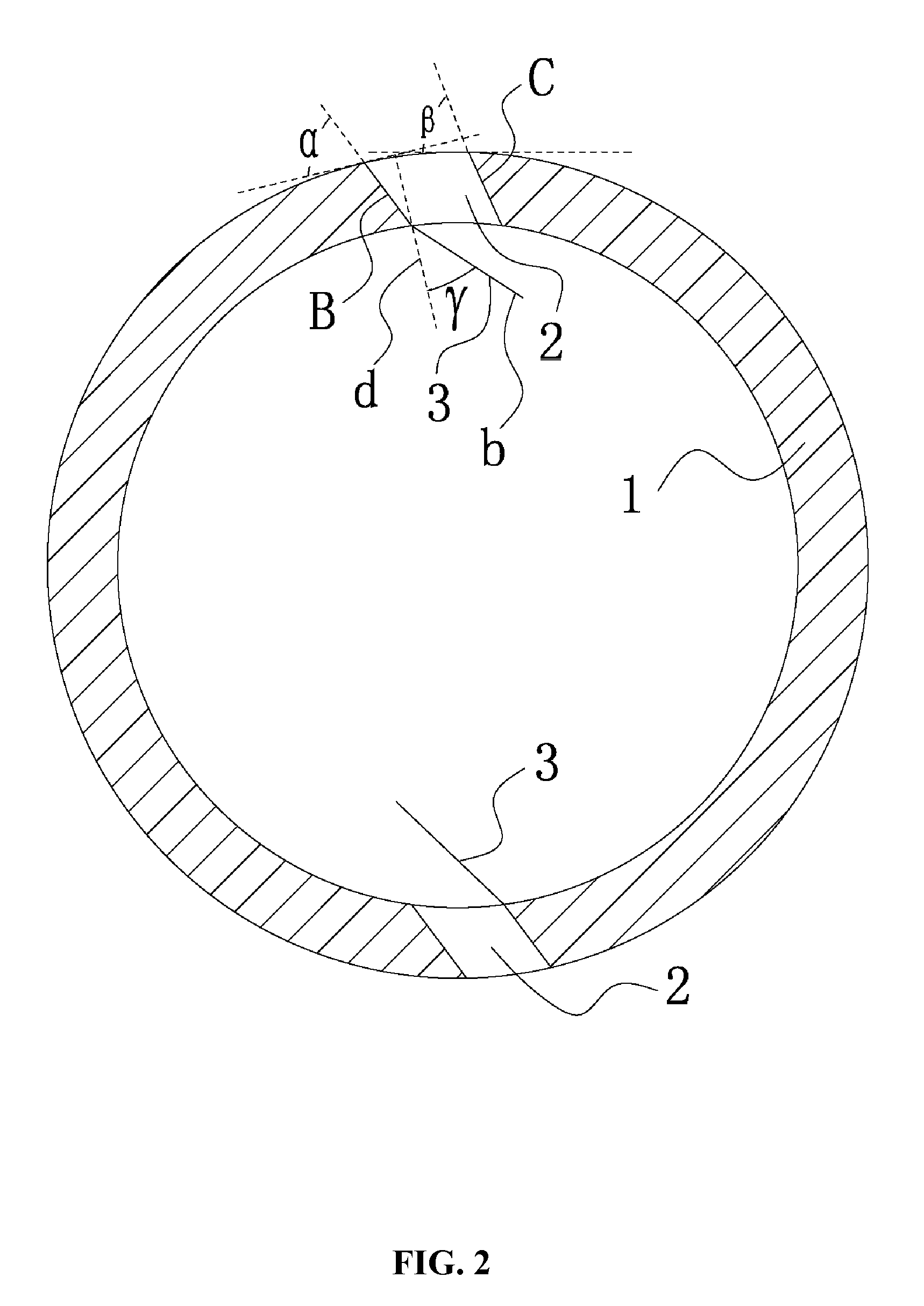
[0026]A chimney, as shown in FIGS. 1-2, comprises: a chimney cylinder 1, and a smoke inlet 2 arranged on a lower part of the chimney cylinder 1. The smoke inlet 2 comprises a first side wall B and a second side wall C on a cross-section of the chimney cylinder 1. A baffle 3 has two ends, one end is disposed on a junction of the first side wall B of the smoke inlet 2 and an inner wall of the chimney cylinder 1, and the other end extends inside and close to a center of the chimney cylinder. The baffle 3 is a straight plate. An angle γ is formed between the baffle 3 and a perpendicular line d of a tangent at a position where the baffle 3 is disposed, and the angle γ is 35°. An angle α is formed between the first side wall B and a first tangent at an intersection of the first side wall B and an outer wall of the chimney cylinder 1, and the angle α is 45°. An angle β is formed between the second side wall C and a second tangent at an intersection of the second side wall C and th...

Example

EXAMPLE 2

[0029]A chimney, as shown in FIGS. 1-4, comprises: a chimney cylinder 1, and a smoke inlet 2 arranged on a lower part of the chimney cylinder 1. The smoke inlet 2 comprises a first side wall B and a second side wall C on a cross-section of the chimney cylinder 1. An angle α is formed between the first side wall B and a first tangent at an intersection of the first side wall B and an outer wall of the chimney cylinder 1, and the angle α is 60°. An angle β is formed between the second side wall C and a second tangent at an intersection of the second side wall C and the outer wall of the chimney cylinder 1, and the angle β is 45°.

[0030]Like Example 1, a baffle 3 has two ends, one end is disposed on a junction of the first side wall B of the smoke inlet 2 and an inner wall of the chimney cylinder 1, and the other end extends inside and close to a center of the chimney cylinder. The baffle is a folded plate shown in FIG. 5, an arc plate shown in FIG. 6, or a curved plate shown i...

Example

EXAMPLE 3

[0032]A chimney, as shown in FIGS. 1 and 8, comprises: a chimney cylinder 1, and a smoke inlet 2 arranged on a lower part of the chimney cylinder 1. The smoke inlet 2 comprises a first side wall B and a second side wall C on a cross-section of the chimney cylinder 1. A baffle 3 has two ends, one end is disposed on a junction of the first side wall B of the smoke inlet 2 and an outer wall of the chimney cylinder 1, and the other end extends inside the chimney cylinder. The baffle 3 is a curved plate. Also, the baffle 3 can be other shapes, and the baffle can be arranged on an outer wall of the chimney cylinder 1, or on the second side wall C of the smoke inlet.

[0033]While particular embodiments of the invention have been shown and described, it will be obvious to those skilled in the art that changes and modifications may be made without departing from the invention in its broader aspects, and therefore, the aim in the appended claims is to cover all such changes and modific...


PUM


Abstract

A chimney, including: a chimney cylinder, and a smoke inlet. The smoke inlet is arranged on a lower part of the chimney cylinder, and includes a first side wall and a second side wall on a cross-section of the chimney cylinder. An angle α is formed between the first side wall and a first tangent at an intersection of the first side wall and an outer wall of the chimney cylinder, and 10°≦α≦90°. An angle β is formed between the second side wall and a second tangent at an intersection of the second side wall and the outer wall of the chimney cylinder, and 10°≦β≦90°.

Description

CROSS-REFERENCE TO RELATED APPLICATIONS[0001]This application is a continuation-in-part of International Patent Application No. PCT / CN2011 / 076184 with an international filing date of Jun. 23, 2011, designating the United States, now pending, and further claims priority benefits to Chinese Patent Application No. 201020240085.8 filed Jun. 29, 2010. The contents of all of the aforementioned applications, including any intervening amendments thereto, are incorporated herein by reference. Inquiries from the public to applicants or assignees concerning this document or the related applications should be directed to: Matthias Scholl P.C., Attn.: Dr. Matthias Scholl Esq., 14781 Memorial Drive, Suite 1319, Houston, Tex. 77079.FIELD OF THE INVENTION[0002]The invention relates to a chimney, and more particularly to a chimney that is non-corrosive, energy-saving, and capable of collecting particulates (soot, dust, etc.).BACKGROUND OF THE INVENTION[0003]A typical chimney includes a flue which is...

Claims


Application Information

Patent Timeline
IPC IPC(8): F23J13/06E04H12/28
CPCE04H12/28F23J13/06F23J11/12
Inventor ZHENG, DEMING
Owner ZHENG DEMING
Why Eureka
Try Eureka