Electrode lead of pacemaker and pacemaker using the same

a technology of electrode lead and electrode lead, which is applied in the direction of insulated conductors, cables, and electrodes, can solve the problems of reducing the working life of electrode lead and pacemaker, damage to implanted electrodes, and even broken electrode leads

Active Publication Date: 2013-05-02
TSINGHUA UNIV +1
View PDF5 Cites 22 Cited by
  • Summary
  • Abstract
  • Description
  • Claims
  • Application Information

AI Technical Summary

Benefits of technology

[0007]What is needed, therefore, is to provide an electrode lead of a pacemaker which has good mechanical strength, toughness, and small physical size, to improve the working life of the electrode lead and the pacemaker using thereof.

Problems solved by technology

The violence of a fierce seizure suffered by a patient or even the energetic long-term normal activities of the patient may cause damage to the implanted electrode lead, or the electrode lead may even be broken.
Therefore, a working life of the electrode lead and of the pacemaker will be decreased, and safety of the patient may be threatened.

Method used


Image

  • Electrode lead of pacemaker and pacemaker using the same
  • Electrode lead of pacemaker and pacemaker using the same
  • Electrode lead of pacemaker and pacemaker using the same

Examples


Embodiment Construction

[0020]The disclosure is illustrated by way of example and not by way of limitation in the figures of the accompanying drawings in which like references indicate similar elements. It should be noted that references to “another,”“an,” or “one” embodiment in this disclosure are not necessarily to the same embodiment, and such references mean at least one.

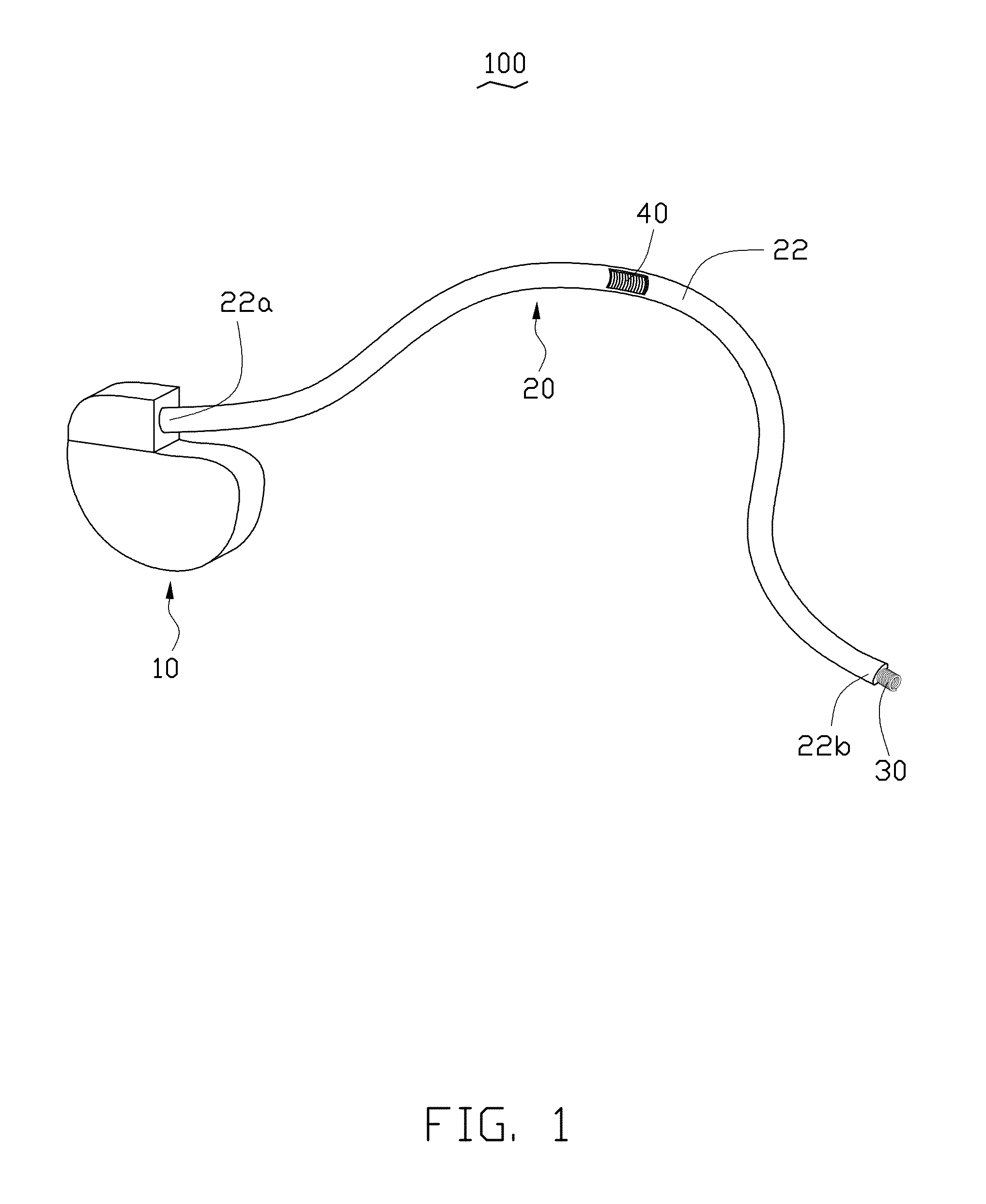
[0021]Referring to FIG. 1, one embodiment of a pacemaker 100 includes a pulse generator 10 and an electrode lead 20 electrically connected with the pulse generator 10. The pulse generator 10 can be used to generate pulse signals to stimulate organs of living beings via the electrode lead 20.

[0022]The pulse generator 10 can include a shell (not labeled), a power source (not shown) and a control circuit (not shown). The power source and the control circuit are packaged in the shell. The power source can provide power for the control circuit. Batteries can be used as the power source, such as lithium ion batteries, fuel cells, and physica...


PUM

PropertyMeasurementUnit
distanceaaaaaaaaaa
thicknessaaaaaaaaaa
diameteraaaaaaaaaa

Abstract

An electrode lead of a pacemaker includes at least one lead wire. The at least one lead wire includes at least one conductive core, a first insulating layer coated on an outer surface of the at least one conductive core, at least one carbon nanotube yarn spirally wound on an outer surface of the first insulating layer, and a second insulating layer coated on the surface of the at least one carbon nanotube yarn. One end of the at least one conductive core protrudes from the first insulating layer to form a naked portion. The at least one carbon nanotube yarn includes a number of carbon nanotubes joined end to end by van der Waals attractive forces. A pacemaker includes a pulse generator and the electrode lead electrically connected with the pulse generator.

Description

[0001]This application claims all benefits accruing under 35 U.S.C. §119 from China Patent Application No. 201110333509.4 filed on Oct. 28, 2011, in the China Intellectual Property Office, the contents of which are hereby incorporated by reference. This application is related to common-assigned applications entitled, “ELECTRODE LEAD OF PACEMAKER AND PACEMAKER USING THE SAME,” filed ______ (Atty. Docket No. US40865); “METHOD FOR MAKING PACEMAKER ELECTRODE LEAD,” filed ______ (Atty. Docket No. US40858); “ELECTRODE LEAD OF PACEMAKER AND PACEMAKER USING THE SAME,” filed ______ (Atty. Docket No. US40859); “ELECTRODE LEAD OF PACEMAKER AND PACEMAKER,” filed ______ (Atty. Docket No. US40860); “PACEMAKERS AND PACEMAKER LEADS,” filed ______ (Atty. Docket No. US40863); “PACEMAKERS AND PACEMAKER LEADS,” filed ______ (Atty. Docket No. US40864); “ELECTRODE LEAD AND PACEMAKER USING THE SAME,” filed ______ (Atty. Docket No. US40867); “ELECTRODE LEAD AND PACEMAKER USING THE SAME,” filed ______ (Atty...

Claims


Application Information

Patent Timeline
Patent Type & Authority Applications(United States)
IPC IPC(8): A61N1/05B82Y5/00
CPCA61N1/056H01B7/048A61N1/362
Inventor FAN, LILIU, LIANGFENG, CHENQIAN, LIWANG, YU-QUANZHAO, WEN-MEI
Owner TSINGHUA UNIV
Why Eureka
Try Eureka