Battery internal state estimating apparatus and battery internal state estimating method

a battery and internal state technology, applied in the field of battery internal state estimating apparatus and battery internal state estimating method, can solve the problems of low learning efficiency, large error, and inability to estimate using such a technique, and achieve the effect of efficient performan

Active Publication Date: 2013-05-02
FURUKAWA ELECTRIC CO LTD +1
View PDF7 Cites 70 Cited by
  • Summary
  • Abstract
  • Description
  • Claims
  • Application Information

AI Technical Summary

Benefits of technology

[0008]In order to solve the aforementioned problem, according to an aspect of the invention, a battery internal state estimating apparatus that estimates an internal state of a battery based on a simulation model of the battery, includes a storing section that stores a plurality of parameters of the simulation model, a detecting section that detects a discharge current flowing from the battery to a load, a selecting section that selects a parameter to be subjected to adaptive learning based on a value of the discharge current detected by the detecting section, and an adaptive learning section that performs adapting learning on a parameter selected by the selecting section. With such a configuration, adaptive learning can be performed efficiently.
[0021]According to an aspect of the invention, a battery internal state estimating apparatus and a battery internal state estimating method capable of efficiently performing an adaptive learning process can be provided, and also a battery internal state estimating apparatus and a battery internal state estimating method capable of calculating the SOH based on a simulation model of a battery can be provided.

Problems solved by technology

The technique disclosed in Patent Document 1 has a drawback that a learning efficiency is low, since parameters are adaptively learned in parallel.
With the technique disclosed in Japanese Laid-Open Patent Application No. 2007-78661, since the SOH is estimated solely based on impedance, there is a drawback that an error is large.
With the technique disclosed in Patent Document 3, since no specific equation for estimating the SOH is disclosed, there is a drawback that the SOH cannot be estimated using such a technique.

Method used


Image

  • Battery internal state estimating apparatus and battery internal state estimating method
  • Battery internal state estimating apparatus and battery internal state estimating method
  • Battery internal state estimating apparatus and battery internal state estimating method

Examples


first embodiment

[0054](A) Explanation of Configuration of First Embodiment

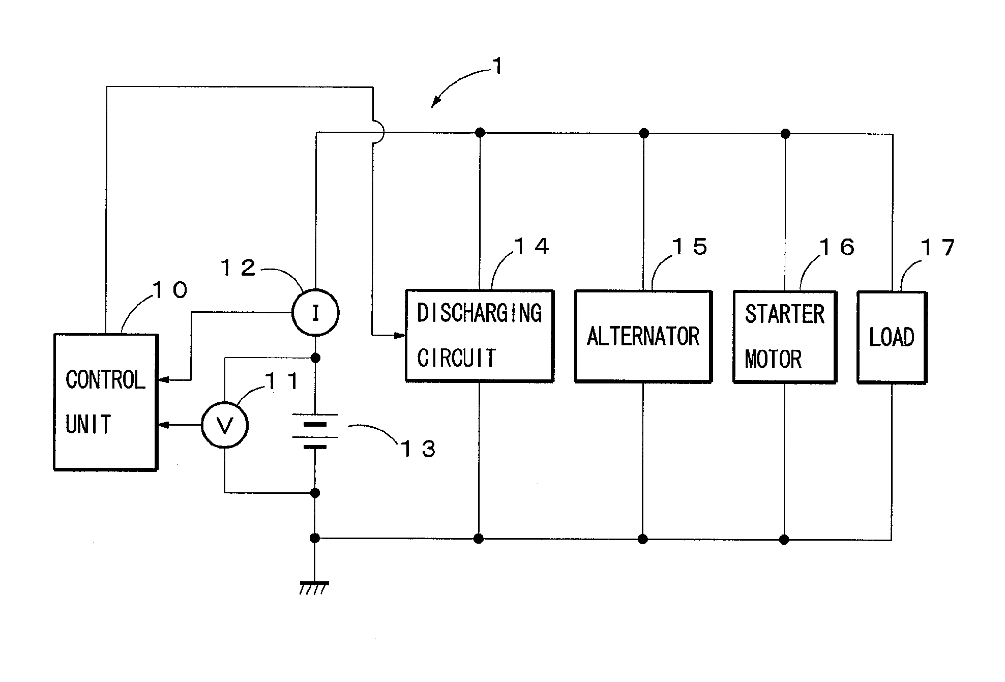
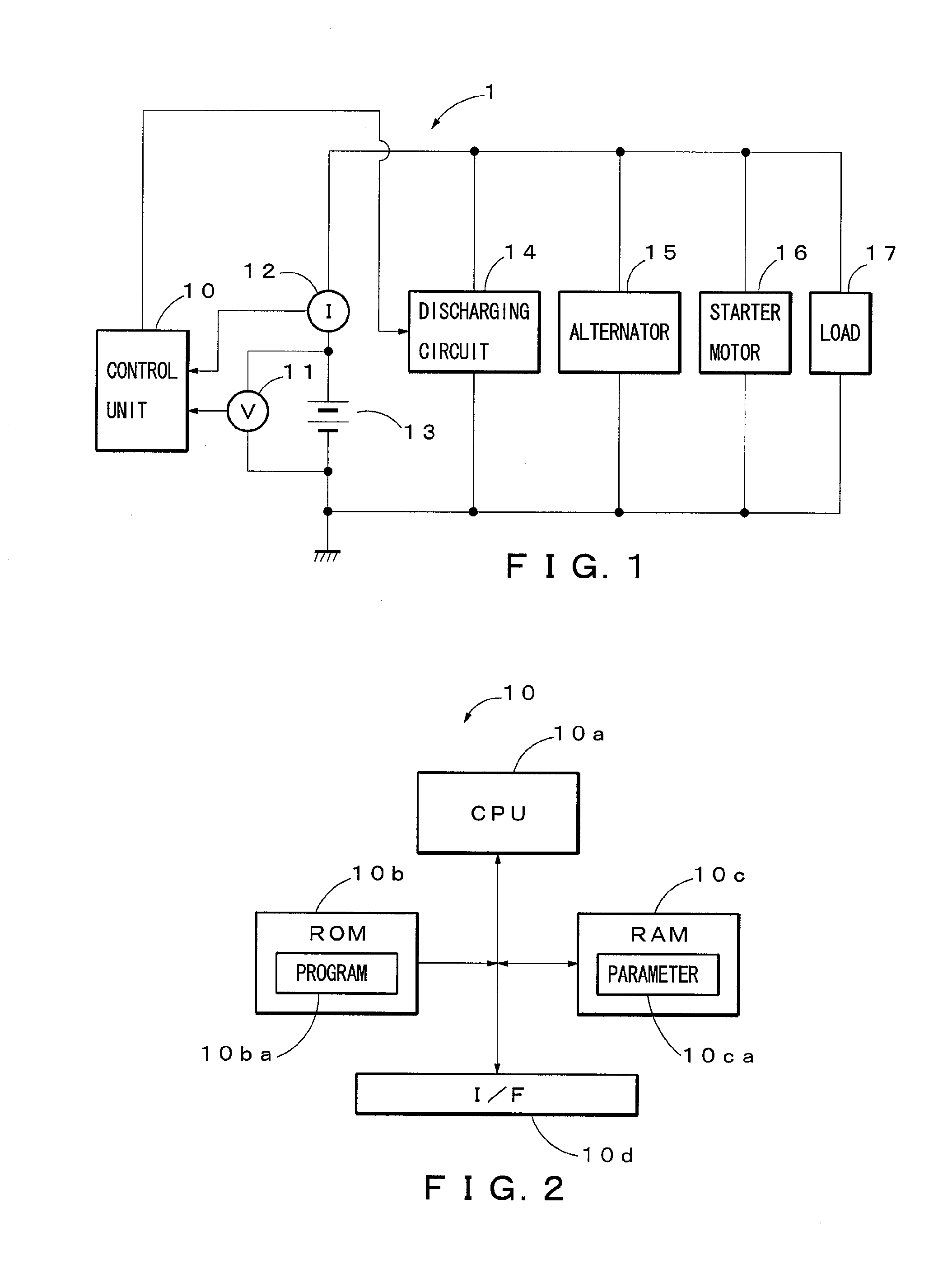
[0055]FIG. 1 is a diagram illustrating an exemplary configuration of a battery internal state estimating apparatus of a first embodiment of the present invention. As shown in FIG. 1, a battery internal state estimating apparatus 1 of the first embodiment includes, as its main constituent elements, a control unit 10, a voltage detecting unit 11 (corresponds to a part of a “detecting section” in the claims), a current detecting unit 12 (corresponds to a part of a “detecting section” in the claims) and a discharging circuit 14, and estimates an internal state of a lead-acid battery 13 (corresponds to a “battery” in the claims). In this example, an alternator 15, a starter motor 16 (corresponds to an “electric motor” in the claims) and a load 17 are connected to the lead-acid battery 13 via the current detecting unit 12. In the first embodiment, explanation will be made for a case where the battery internal state estimating appar...

second embodiment

[0113](D) Explanation of Configuration of Second Embodiment

[0114]FIG. 1 is a diagram illustrating an exemplary configuration of a battery internal state estimating apparatus of a second embodiment of the present invention. As shown in FIG. 1, a battery internal state estimating apparatus 1 of the second embodiment includes, as its main constituent elements, a control unit 10, a voltage detecting unit 11 (corresponds to a part of “actual measurement section” and a part of “observation section” in the claims), a current detecting unit 12 (corresponds to a part of “actual measurement section” and a part of “observation section” in the claims) and a discharging circuit 14, and estimates an internal state of a lead-acid battery 13 (corresponds to “a battery” in the claims). In this exemplary configuration, an alternator 15, a starter motor 16 and a load 17 are connected to the lead-acid battery 13 via the current detecting unit 12. In the second embodiment, an explanation will be made fo...

third embodiment

[0146](F) Explanation of Third Embodiment

[0147]The third embodiment differs from the second embodiment in that an equation for calculating the SOH is different. Other configurations are similar to those of the second embodiment. More specifically, in the second embodiment, the SOH is calculated using equation (18), whereas, in the third embodiment, the SOH is calculated using equation (20) described below.

SOH=C1·η+C2·Rmeas+C3  (20)

[0148]where

[0149]C1, C2 and C3 are constants which are determined in advance (e.g., constants determined depending on the type of lead-acid battery 13 and obtained by actual measurement);

[0150]η is a parameter indicating a change over time of the resistance R0; and

[0151]Rmeas is an actual measured value of the internal resistance.

[0152]It is to be noted that η and Rmeas are the same parameters as described above, and C1, C2 and C3 are separately calculated from the aforementioned constants. As a specific example, in a case where the 20 hour rate (0.05 C) r...


PUM


Abstract

To learn a parameter of a simulation model of a battery efficiently. A battery internal state estimating apparatus, estimating an internal state of a battery based on a simulation model of the battery, includes a storing section (RAM10c) that stores a plurality of parameters of the simulation model, a detecting section (I / F10d) that detects a discharge current flowing from the battery to a load, a selecting section (CPU 10a) that selects a parameter to be subjected to adaptive learning based on a value of the discharge current detected by the detecting section, and an adaptive learning section (CPU 10a) that performs adapting learning on a parameter selected by the selecting section.

Description

BACKGROUND[0001]1. Technical Field[0002]The present invention relates to a battery internal state estimating apparatus and a battery internal state estimating method.[0003]2. Background Art[0004]A method of estimating an internal state of a battery such as, for example, a technique disclosed in Japanese Laid-Open Patent Application No. 2007-187534 is known. More specifically, Japanese Laid-Open Patent Application No. 2007-187534 discloses a technique in which a Kalman filter is used in estimating an SOC (State of Charge) indicating a state of charge of a battery.[0005]Japanese Laid-Open Patent Application No. 2007-78661 discloses a technique in which an SOH (State of Health) of a lead-acid battery is estimated based on impedance. Further, Japanese Laid-Open Patent Application No. 2007-518973 discloses a method in which a neural network is used in estimating an SOC (State of Charge) of the lead-acid battery.SUMMARY[0006]The technique disclosed in Patent Document 1 has a drawback that...

Claims


Application Information

Patent Timeline
Patent Type & Authority Applications(United States)
IPC IPC(8): G01R31/36G06F17/00
CPCG01R31/3606G06F17/00H01M10/48H01M10/06G01R31/382G01R31/367G01R31/392Y02E60/10
Inventor MITSUYAMA, TAIJISUGIMURA, TAKEZOSATO, ETSUZOKOVATS, ANTAL
Owner FURUKAWA ELECTRIC CO LTD
Why Eureka
Try Eureka