Disc Mower Blades

a mower blade and disc technology, applied in the field of disc mower blades, can solve the problems of cutting blades subjected to extreme abrasive wear conditions, cutter blades becoming dull prior to the rest of the blade, further wear and dulling of the blade tip, etc., and achieve the effect of reducing the tendency of vegetation

Inactive Publication Date: 2013-05-09
KONDEX CORP
View PDF42 Cites 30 Cited by
  • Summary
  • Abstract
  • Description
  • Claims
  • Application Information

AI Technical Summary

Benefits of technology

[0007]In one aspect, embodiments of the invention provide a disc mower cutter blade for cutting vegetation. The disc mower cutter blade includes a disc mower cutter blade body that has a mounting aperture, and a knife cutting edge spaced from the mounting aperture. The knife cutting edge extends toward a tip of the disc mower cutter blade. The disc mower cutter blade further includes a means for reducing the tendency of vegetation from slipping off and around the knife cutting edge and the tip.
[0008]In various embodiments, the means for reducing the tendency of vegetation to slip off and around the knife cutting edge and tip includes at least one of: (1) a plurality of serrations distributed along the knife cutting edge, (2) a concave curvature formed into the knife cutting edge, and / or (3) a winglet integrally formed into the blade body at a tip end remote from the mounting aperture.
[0011]Additionally, the means for reducing the tendency of vegetation from slipping off and around the knife cutting edge and the tip include a concave curvature formed at least partially into the leading section. The concave curvature extends at a radius of curvature of between 1 and 3 inches in certain embodiments, and in other embodiments, the radius of curvature extends between 3 and 10 inches.

Problems solved by technology

In the use of these mowing machines, the cutter blades are subjected to extreme abrasive wear conditions particularly concentrated at the tip of the cutter blade.
This leads to the tip of the cutter blade becoming dull prior to the rest of the blade.
Because the tip of the blade is dull, the crops being cut tend to slide past the outer edge of the cutter blade.
The sliding effect causes further wear and dulling of the tip of the blade because the crops are sliding off the end of the blade as opposed to being cut.
Further, the stalks of the plant tend to be abrasive in and of themselves, which also contributes to the dulling of the cutter blade.
Furthermore, because the cutter blades are worn and dull at the tip causing the crops to slide past the tip instead of being severed, there is a cutting efficiency loss.
This cutting efficiency loss also results in a non-clean cut that is not at a consistent height from ground level, where the crops are anchored by their root structure.
This further harms the re-growth effort of the crop.
Also, because the cutter blades are not cutting the crop upon impact, the crops slide to the dullest part of the blade to sever the crop, which leads to a higher required force to keep the discs spinning at the desired velocity.
The higher force required leads to higher horse power requirements and increased fuel usage that in turn increase component and maintenance costs for the mowing machine.

Method used


Image

  • Disc Mower Blades
  • Disc Mower Blades
  • Disc Mower Blades

Examples


Embodiment Construction

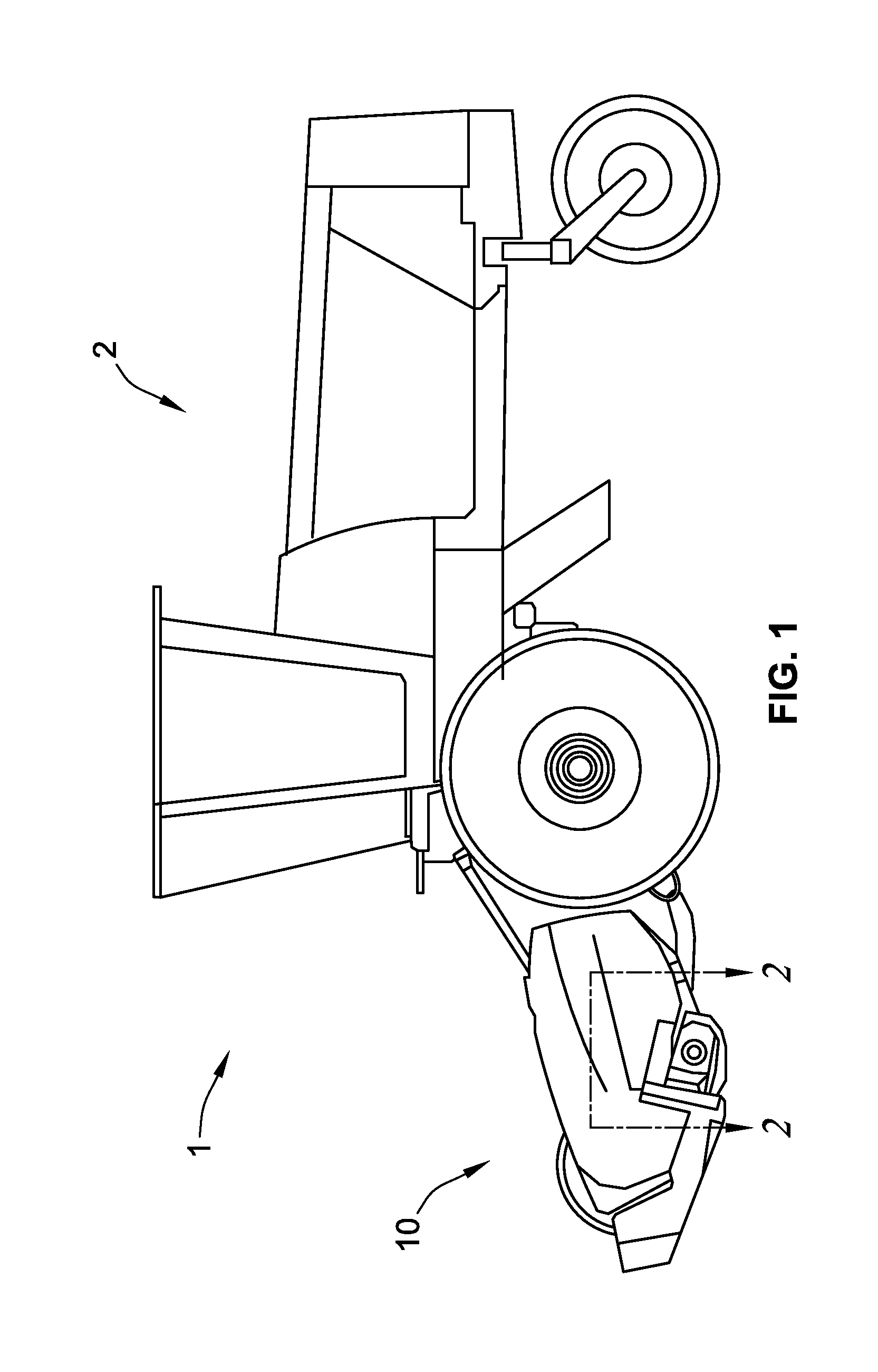
[0029]FIG. 1 illustrates a tractor pulling a mowing machine 1 that includes a tractor 2 and a mowing machine 10. The mowing machine 10 may either be self-propelled or pulled / powered by the tractor 2.

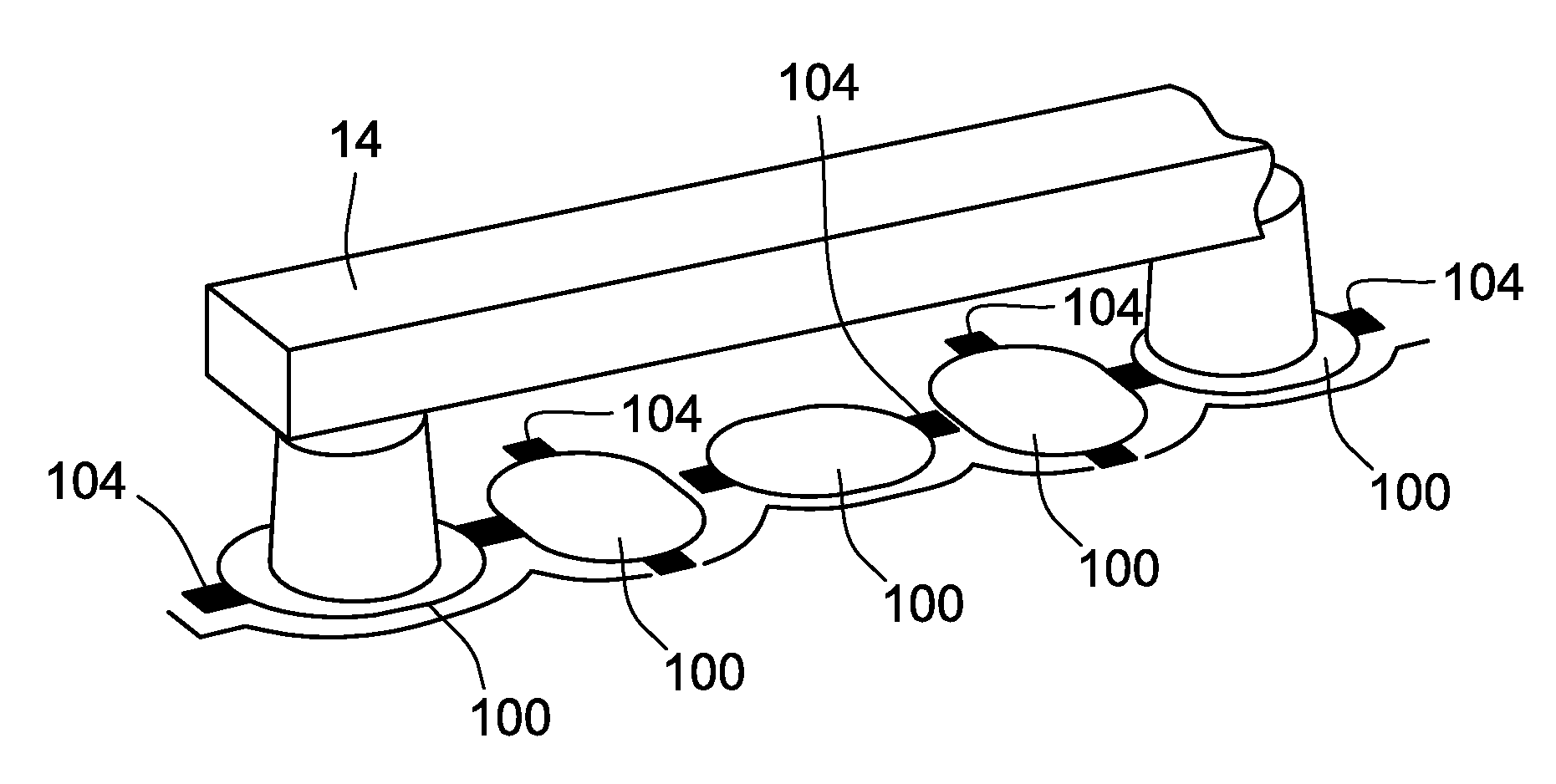
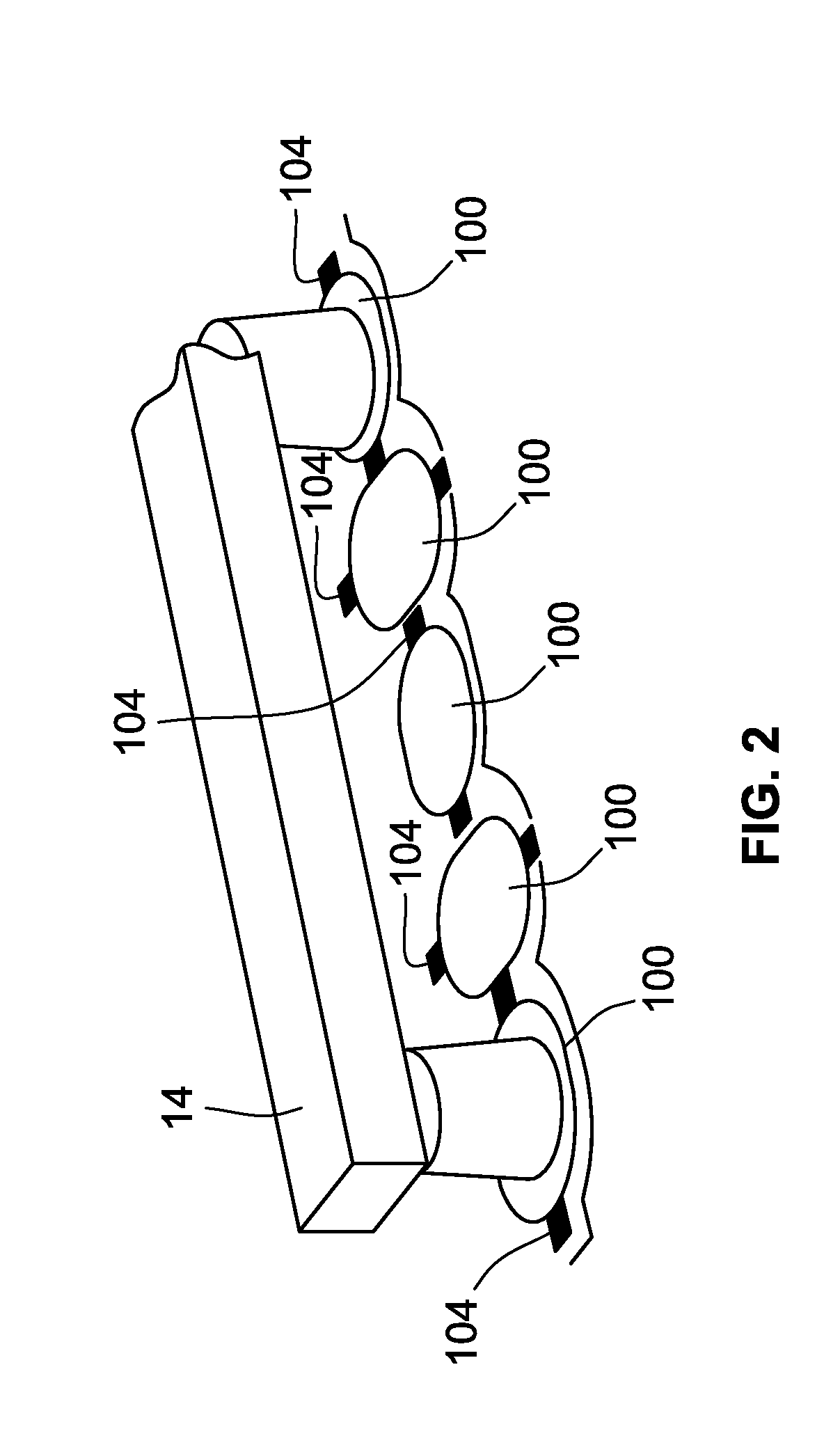
[0030]FIG. 2 illustrates a disc cutter bar 14. Disc cutter bar 14 supports a plurality of rotary cutter modules 100, which in turn support a plurality of curter blades 104. Disc cutter bar 14 is part of the mowing machine10, from FIG. 1.

[0031]FIG. 3 illustrates a schematic view of a mowing machine 10. The mowing machine 10 includes a drive unit 12 for driving a rotary cutter bar 14. The rotary cutter bar 14 includes a plurality of rotary cutter modules 100 that each contain a plurality of cutter blades 104 (see FIG. 2). While the mowing machine 10 is illustrated as including a plurality of rotary cutter modules 100, it is contemplated that as few as one rotary cutter module 100 could be employed in certain applications.

[0032]FIG. 4 illustrates an isometric view of the rotary cutter modul...


PUM


Abstract

An improved cutter blade or disc mower blade is provided having structure to reduce the tendency of vegetation to slip off and around the blade edge and tip. The disc mower blade is attached to a rotary cutter module and driven by a mowing machine. In one aspect of the disc mower blade, the disc mower blade includes a knife edge with serrations distributed along the edge such that vegetation does not slide along the edge during operation of the mowing machine. Further, another aspect of the mower blade is that the knife edge may be curved so as to prevent the vegetation from sliding along the edge during operation of the mowing machine. In another aspect, the disc mower blade includes a winglet disposed at a tip of the blade such that vegetation cannot slide past the blade during operation of the mowing machine.

Description

CROSS-REFERENCE TO RELATED PATENT APPLICATIONS[0001]This patent application claims the benefit of U.S. Provisional Patent Application No. 61 / 556,348, filed Nov. 7, 2011, the entire teachings and disclosure of which are incorporated herein by reference thereto.FIELD OF THE INVENTION[0002]This invention generally relates to disc mower blades (also referred to as knives).BACKGROUND OF THE INVENTION[0003]Generally, disc style cutter bars are used on a mowing machine to sever standing crops in an agricultural setting or grass in a lawn application. A disc style cutter bar typically includes several rotating discs that carry cutter blades that sever standing crops upon impact.[0004]In the use of these mowing machines, the cutter blades are subjected to extreme abrasive wear conditions particularly concentrated at the tip of the cutter blade. This leads to the tip of the cutter blade becoming dull prior to the rest of the blade. Because the tip of the blade is dull, the crops being cut ten...

Claims


Application Information

Patent Timeline
Patent Type & Authority Applications(United States)
IPC IPC(8): A01D34/73A01D34/76
CPCA01D34/736A01D34/664
Inventor JOHNSON, KEITH A.STOFFEL, NEAL J.
Owner KONDEX CORP
Why Eureka
Try Eureka