Variable displacement hydraulic pump/motor with hydrostatic valve plate

a hydraulic pump/motor and valve plate technology, applied in the direction of positive displacement engines, reciprocating piston engines, liquid engines, etc., can solve the problems of large size, more complex design of valve plate, and generally limited maximum total displacement angles of valve plate designs, so as to facilitate the creation of hydrostatic pads, reduce potential wear, and eliminate negative traits

Inactive Publication Date: 2013-05-09
PARKER HANNIFIN CORP
View PDF9 Cites 0 Cited by
  • Summary
  • Abstract
  • Description
  • Claims
  • Application Information

AI Technical Summary

Benefits of technology

[0005]The present invention provides an improved design of variable displacement hydraulic axial piston machine with advantages of both the hydrostatic sliding valve plate and yoke concepts in a single design, while eliminating or minimizing negative traits of both. The sliding valve plate in this design facilitates the creation of a hydrostatic pad between the sliding valve plate and the casing to reduce potential wear and reduce sliding friction. The sliding valve plate also has an operable running surface for engaging the piston barrel that is easier to machine flat. And finally, unlike the separate components in previous designs the sliding valve plate integrates the support functions of a valve plate and valve plate timing into a single unit. The machine provided by the invention also includes a separate flow tube for directing high pressure fluid to and / or from the sliding valve plate. The flow tube provided by the invention can translate axially as the sliding valve plate pivots about a pivot axis when the displacement changes, thereby reducing the tolerance requirements. Another advantage provided by the flow tube is that it allows for the connection of a feedback sensor directly on the pivot axis to more accurately monitor the angular position of the sliding valve plate about the pivot axis.

Problems solved by technology

While the valve plate design generally is compact, simple, and hydrostatically supports the load imparted on the machine casing, valve plate designs generally provide limited maximum total displacement angles due to a reduction in flow area as the valve plate is rotated.
This is particularly disadvantageous for applications having reversing flow, i.e., applications where the machine is used as both a pump and a motor.
In contrast, yoke designs allow for ease of porting even through large displacement angle ranges, but tend to be larger and more complex than valve plate designs.
Further, yoke designs often are complex to manufacture and result in the need for extremely accurate manufacturing tolerances amongst various parts.

Method used


Image

  • Variable displacement hydraulic pump/motor with hydrostatic valve plate
  • Variable displacement hydraulic pump/motor with hydrostatic valve plate
  • Variable displacement hydraulic pump/motor with hydrostatic valve plate

Examples


Embodiment Construction

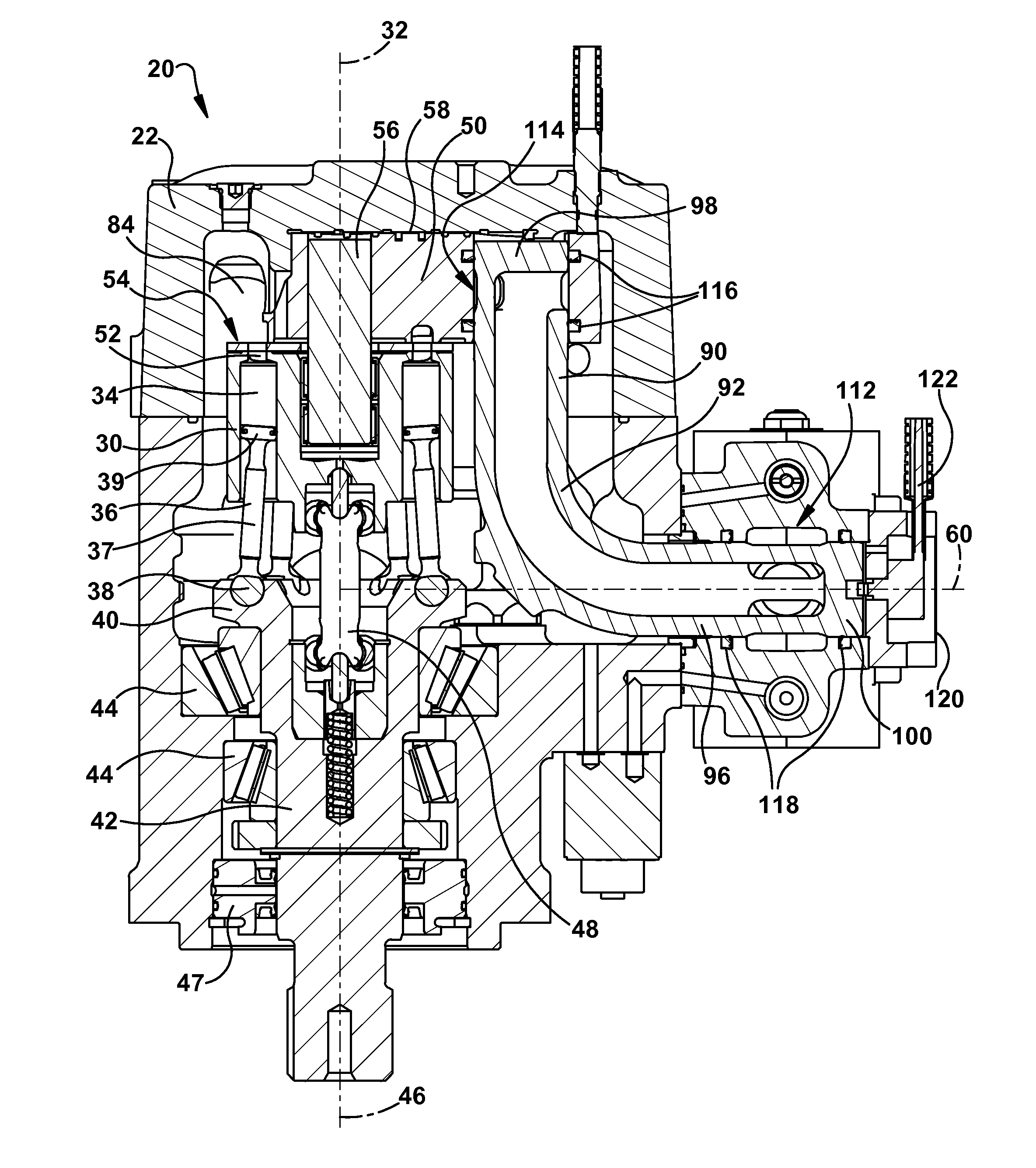
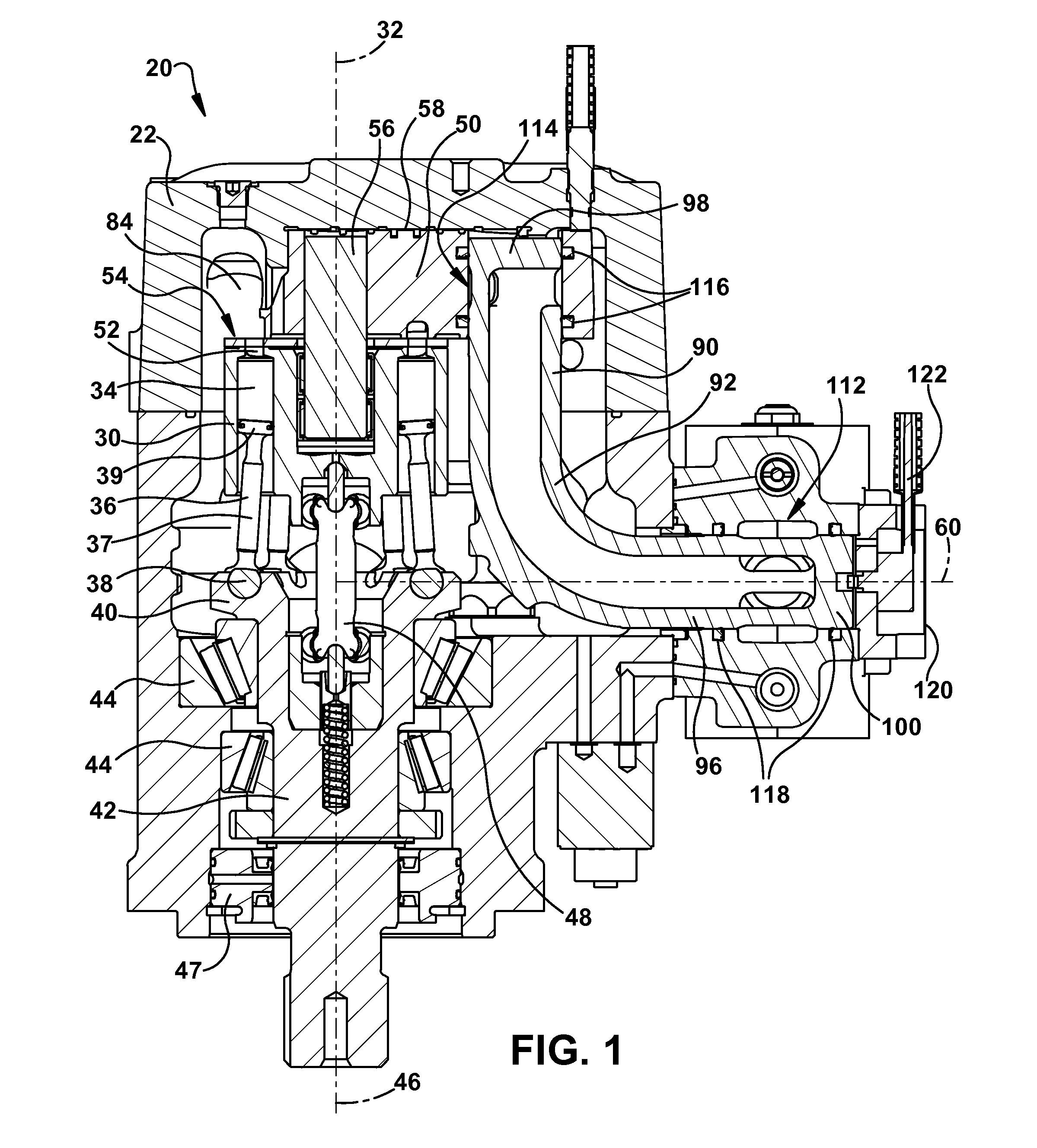
[0033]The present invention provides an improved design for a hydrostatic axial piston machine, such as a hydraulic pump or a hydraulic motor, or a machine that can operate as either a pump or a motor. This design is particularly applicable to a variable displacement axial piston machine.

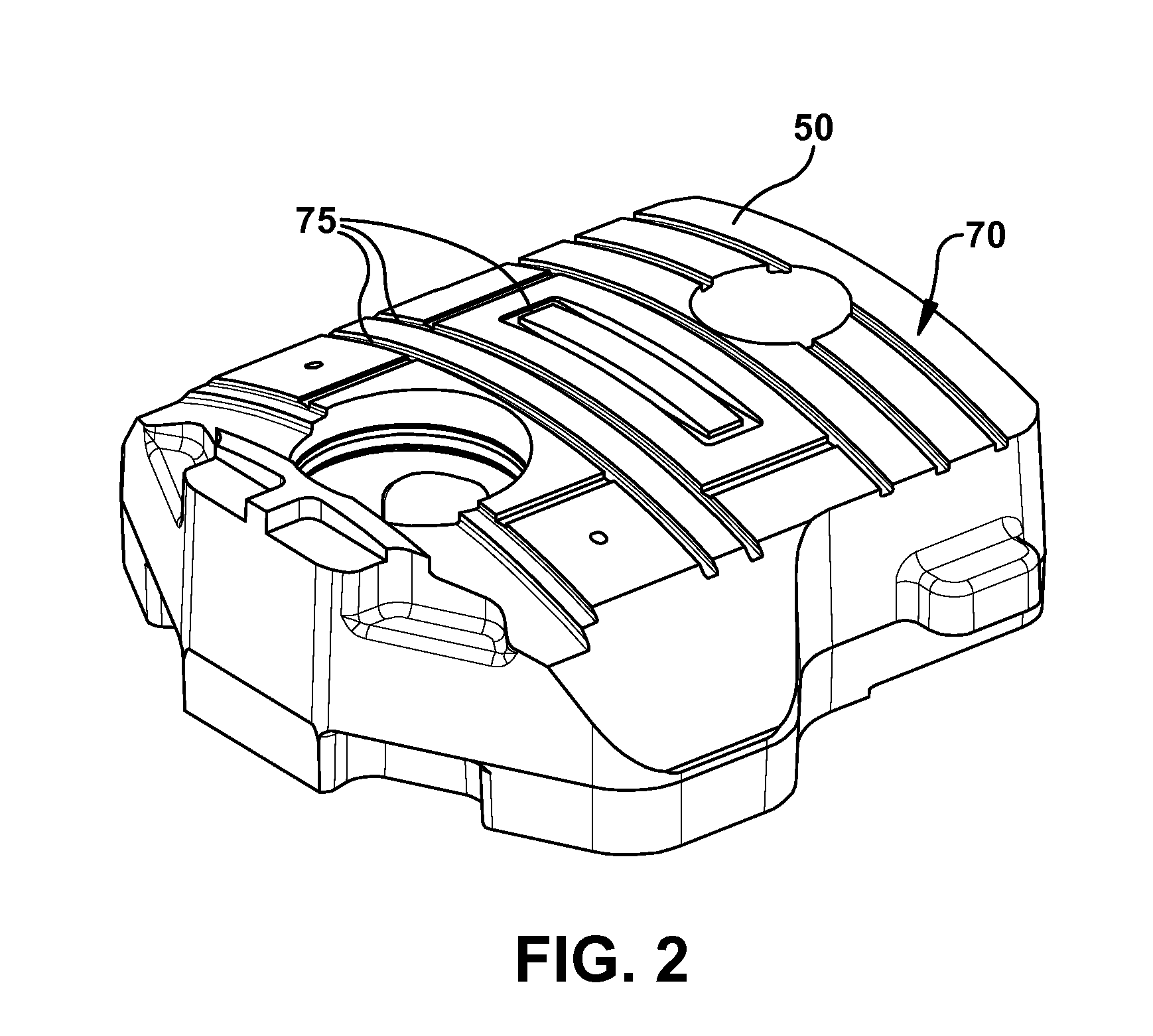
[0034]The axial piston machine provided by the invention provides several advantages over prior axial piston machines. For example, the machine includes a valve plate that has a hydrostatic bearing surface facing the machine casing to reduce potential wear and to reduce sliding friction; the valve plate has an easily-machined flat running surface; and the valve plate integrates hydrostatic valve plate support and valve plate timing into the flat running surface of the valve plate.

[0035]Additionally, the hydrostatic piston machine includes a flow tube separate from the valve plate. As described in additional detail below, the flow tube and the valve plate are not fixed relative to one another so the ...


PUM


Abstract

A variable displacement hydraulic axial piston machine includes (a) a housing having an outlet opening; (b) a barrel mounted in the housing for rotation about a rotation axis; (c) a plurality of pistons movable in respective bores in the barrel; (d) a valve plate coupled to the barrel and having a fluid passage therein that ends at an outlet opening; and (e) a flow tube connecting the outlet opening in the valve plate to the outlet opening in the housing. The barrel and the valve plate are pivotally movable together about a pivot axis transverse the rotation axis for varying the displacement of the pistons in the bores. An end of the flow tube connects to the valve plate while allowing for axial movement of the flow tube relative to the valve plate in a direction parallel to the rotational axis of the barrel.

Description

RELATED APPLICATIONS[0001]This application claims the benefit of U.S. Provisional Application No. 61 / 369,209 filed Jul. 30, 2010, which is hereby incorporated herein by reference.FIELD OF THE INVENTION[0002]This invention relates to a hydraulic axial piston machine and, more particularly, to a variable displacement hydraulic pump / motor with a hydrostatic valve plate.BACKGROUND OF THE INVENTION[0003]A hydraulic axial piston machine has a barrel rotatably mounted within a pump housing. The barrel includes a plurality of circumferentially equally-spaced bores in which pistons reciprocate. Each piston bore has a port in the end of the barrel that lies against a valve plate that defines delivery and exhaust ports. As the barrel rotates, each piston bore port sequentially traverses the delivery and exhaust ports in the valve plate. In a pump mode, as each piston bore port traverses the delivery port low pressure fluid is drawn into the piston bore. When the piston bore port traverses the ...

Claims


Application Information

Patent Timeline
Patent Type & Authority Applications(United States)
IPC IPC(8): F04B1/30
CPCF03C1/0636F03C1/0655F03C1/0694F04B1/30F04B1/2042F04B1/328F04B1/20
Inventor LARKIN, BRUCEHARTTER, LARRYKORENKIEWICZ, PAUL
Owner PARKER HANNIFIN CORP
Why Eureka
Try Eureka