Processes for precutting laminated flocked articles

a technology of laminated flocked and precutting, which is applied in the field of decorative articles, can solve the problems of inability to meet the needs of customers, and inability to meet the needs of customers, and achieve the effects of reducing the cost of production

Inactive Publication Date: 2013-05-09
HIGH VOLTAGE GRAPHICS
View PDF5 Cites 17 Cited by
  • Summary
  • Abstract
  • Description
  • Claims
  • Application Information

AI Technical Summary

Benefits of technology

[0011]The positioning of cutting and weeding operations before heating / activating (full or partial) of the adhesive film can have numerous benefits. By performing cutting before lamination, the transfer is cut before the transfer sheet is attached to the flock. By cutting on a relatively smooth, flat and fine gauge release sheet or the adhesive film itself, adjustment of the cutting device cut can be precise, much faster, and without influence from the fiber layer. The unwanted portion to be discarded can be peeled away easily and disposed of before lamination.
[0012]Another object of the present invention is to provide a stretchable transfer or design that prevents the flock fiber adhesive layer from becoming detached from the design or transfer, before, during and after the transfer or design is stretched.
[0013]Yet another object of the present invention is to provide a stretchable or elastic design that has shape memory and will reform, after being stretched, substantially to its original shape and size without loss of original design integrity.
[0014]Still yet another object of the present invention is to provide a stretchable or elastic design that, when stretched to a high degree, evidences an increase in the inter flock distance (i.e., the horizontal space between individual fibers) without the flock becoming disengaged from the substrate.
[0015]At least one embodiment of the present invention describes a flocked stretchable design and a process for producing a flocked stretchable design or transfer. The design can have shape memory even when stretched to a high degree.

Problems solved by technology

When cutting is performed after lamination, it has been discovered that the final product can have flaws.
For very fine and delicate designs, such as a 12-point font lettering it is impractical at best, impossible at worst, to make cutting dies so other cutting methods like laser cutting are preferred.
The challenge is to focus the laser precisely on the film layer, which becomes even more serious if the laser beam is cutting further away from the mirror.
This results in a more extreme angle such that any inaccuracy in laser focus causes the laser to either not cut far enough into the film or cut too far and past the film, such as into the flock fiber layer.
Other problems with laser cutters include not only the inconsistency of the clean cut (e.g., little strings remain making removal of the part to be weeded out very difficult to do) but also jagged or wavy edges.
While not wishing to be bound by any theory, it is believed that the inconsistency is the result of a slightly uneven fiber surface and / or the flowing of the adhesive film onto and into the flock fibers adjacent to the cut.

Method used


Image

  • Processes for precutting laminated flocked articles
  • Processes for precutting laminated flocked articles
  • Processes for precutting laminated flocked articles

Examples


first embodiment

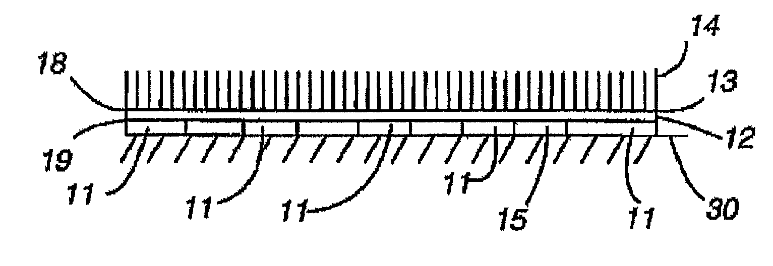
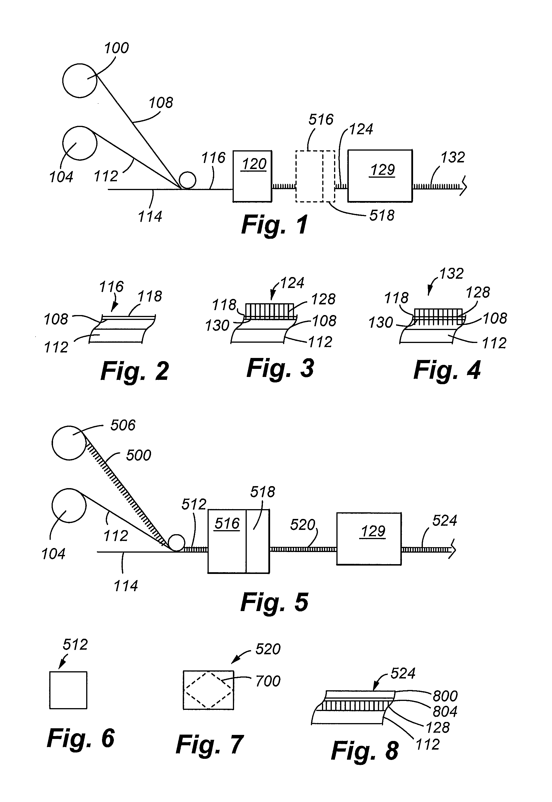
[0050]Referring to FIGS. 1-5, a system for manufacturing a flocked article according to the present invention is depicted. The system includes a first roll 100 containing a permanent (pre-formed) adhesive film 108 and a second roll 104 containing a substrate film 112. The second roll 104 and substrate film 112 is omitted in certain applications. The pre-formed films 108 and / or 112 are contacted one on top of the other on a continuous running web line 114.

[0051]The adhesive film 108 can be any suitable adhesive film for the application. As will be appreciated, an “adhesive” is any substance, whether inorganic or organic, natural or synthetic, that is capable of bonding other substances together, typically by surface attachment. Examples of suitable adhesives include high temperature adhesives, such as polybenzimidazoles and silica-boric acid mixtures or cermets, hot-melt adhesives, thermoset adhesives, thermoplastic adhesives, and polyurethane. “Hot-melt adhesives” generally refer to...

second embodiment

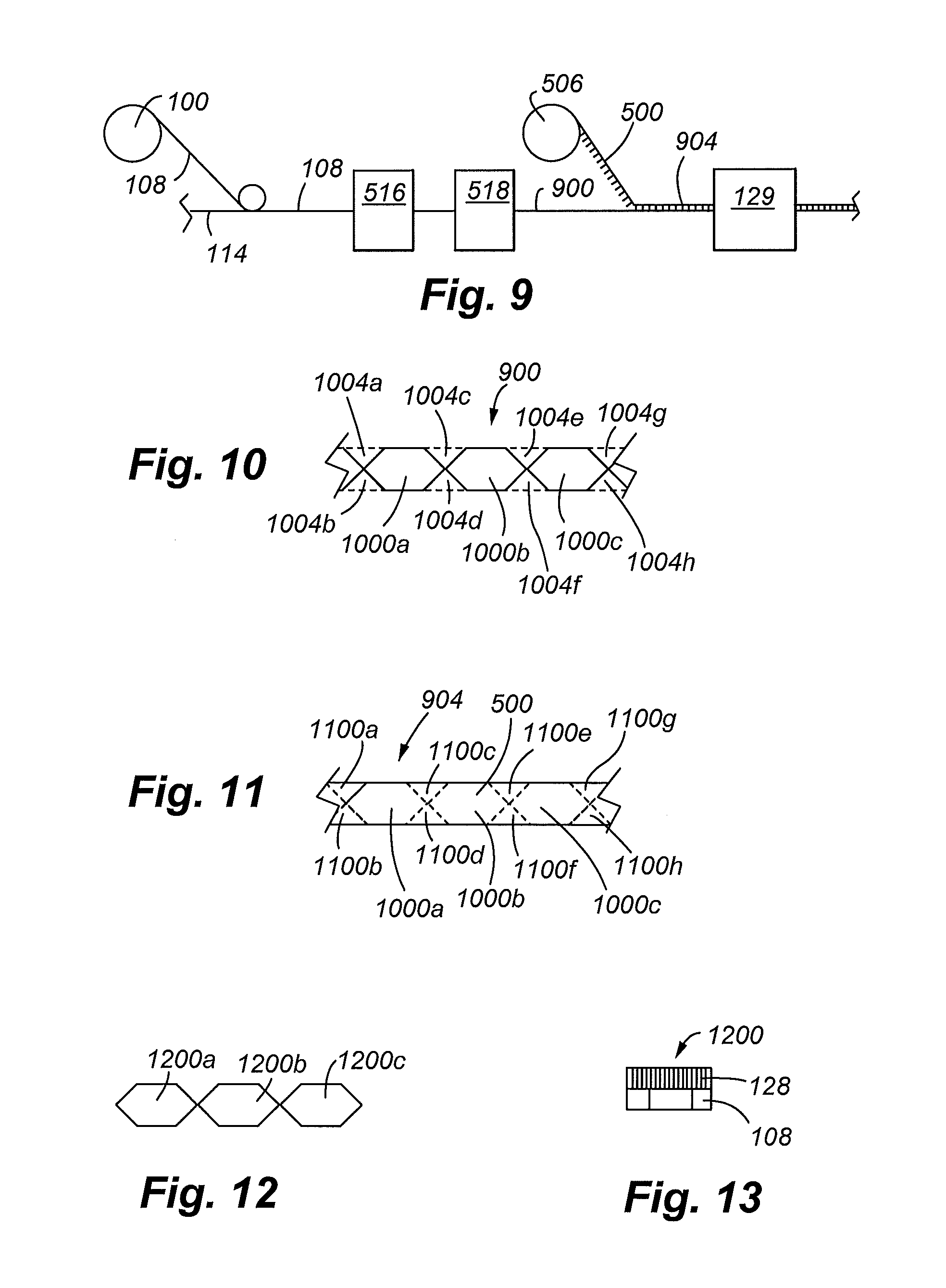
[0064]the present invention will now be discussed with reference to FIGS. 5-8.

[0065]As in the prior embodiment, the system includes first and second rolls 506 and 104. The first roll contains a flocked transfer sheet 500 and the second roll the adhesive film 112. The flocked transfer sheet 500 includes a release sheet 800 and release adhesive 804.

[0066]The release sheet 800 can be any suitable transfer carrier that is formable and dimensionally stable with the flock. Examples of other types of suitable transfer carriers include plastic films. The sheet is preferably a discontinuous sheet or a running web line material. The carrier sheet or film has been found to assist in robotically feeding the mold insert or mold insert film into the forming tool and / or the mold itself. A vacuum is able to pick up the mold insert or mold insert film and transport and position the insert at a desired location in the forming tool / open mold. Other techniques to establish a vacuum connection include (...


PUM

PropertyMeasurementUnit
elongationaaaaaaaaaa
thicknessaaaaaaaaaa
thicknessaaaaaaaaaa

Abstract

A process for forming a flocked article is provided that includes the steps of: (a) cutting a pre-formed or solid adhesive film into a desired shape; (b) removing a first portion of the cut pre-formed adhesive film from a second portion of the cut pre-formed adhesive film; and (c) heating and applying pressure to the cut pre-formed adhesive film to adhere the film to flock to form a flocked article.

Description

CROSS REFERENCE TO RELATED APPLICATIONS[0001]The present application is a continuation-in-part of U.S. patent application Ser. No. 12 / 874,784, filed Sep. 2, 2010, which is a continuation of U.S. patent application Ser. No. 11 / 849,840, filed Sep. 4, 2007, which is a continuation-in-part of U.S. patent applications having Ser. Nos. (a) 10 / 961,821, filed Oct. 7, 2004, which claims the benefits of U.S. Provisional Application Ser. No. 60 / 509,834, filed Oct. 8, 2003, entitled “Process for Forming Flocked Articles”; and (b) 09 / 735,721, filed Dec. 13, 2000, which is a continuation-in-part of U.S. application Ser. No. 09 / 621,830; and (c) Ser. No. 09 / 621,830, filed Jul. 24, 2000, each of which is incorporated herein by this reference.FIELD OF THE INVENTION[0002]The present invention is directed generally to decorative articles and specifically to flocked articles.BACKGROUND[0003]Flocked decorative articles are gaining in popularity. Flocking involves applying short monofilament fibers, usual...

Claims


Application Information

Patent Timeline
Patent Type & Authority Applications(United States)
IPC IPC(8): B32B5/16B32B37/02B32B37/00B32B7/12
CPCB32B5/16B32B7/12B32B37/02B32B37/025B29K2715/006B05D1/16B29K2713/00B32B33/00B32B38/0004B44C1/18D04H11/00B29C2045/14114B32B2037/1223B29C45/14811Y10T428/23943Y10T428/23914
Inventor ABRAMS, LOUIS BROWN
Owner HIGH VOLTAGE GRAPHICS
Why Eureka
Try Eureka