
Method and system for controlling relative position between vehicles using a mobile base station

Inactive Publication Date: 2013-05-09
HYUNDAI MOTOR CO LTD
View PDF9 Cites 77 Cited by
  • Summary
  • Abstract
  • Description
  • Claims
  • Application Information

AI Technical Summary

Benefits of technology

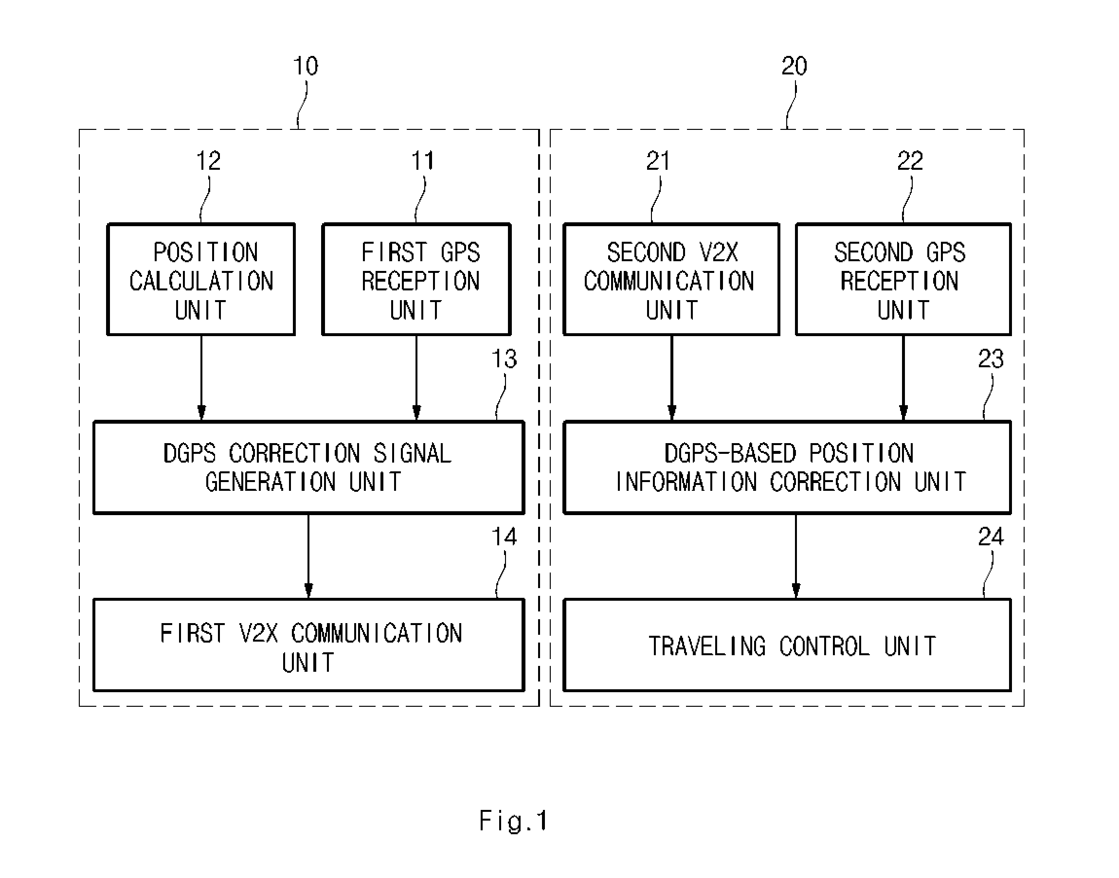
The patent describes a method and system for controlling the relative position between vehicles using a mobile base station. The mobile base station is a vehicle that acts as a reference point for positioning other vehicles using a differential global positioning system (DGPS). By using this mobile base station, the system can improve the accuracy of positioning and control vehicles through vehicle-to-vehicle communication. This approach is cost-effective and may be used for non-autonomous vehicle platooning, providing safety and guidance for the direction and position of travel based on the position information received from the mobile base station.

Problems solved by technology

In order for most GPS devices to work properly, however, there typically must be an unobstructed line of sight to four or more GPS satellites.
Thus, the degree of accuracy for these systems is not as proficient as most automotive manufactures would like in order to provide a high degree of accuracy as to the vehicle's current location.
However, since a complex technology for accurately controlling a relative position between vehicles using the DGPS, and the like is required, a significant cost is required to mount necessary sensors and equipment in each vehicle.
The DGPS, however, as noted above is limited by the location of the base station which is fixed.
Thus, when a commercial DGPS correction data is used and a vehicle is located too far away from the base station, it is impossible to improve position accuracy even when the DGPS is used.

Method used


Image

  • Method and system for controlling relative position between vehicles using a mobile base station
  • Method and system for controlling relative position between vehicles using a mobile base station
  • Method and system for controlling relative position between vehicles using a mobile base station

Examples


Embodiment Construction

[0027]Reference will now be made in detail to various embodiments of the present invention(s), examples of which are illustrated in the accompanying drawings and described below. Like reference numerals in the drawings denote like elements. When it is determined that detailed description of a configuration or a function in the related disclosure interrupts understandings of embodiments in description of the embodiments of the invention, the detailed description will be omitted.

[0028]It is understood that the term “vehicle” or “vehicular” or other similar term as used herein is inclusive of motor vehicles in general such as passenger automobiles including sports utility vehicles (SUV), buses, trucks, various commercial vehicles, watercraft including a variety of boats and ships, aircraft, and the like, and includes hybrid vehicles, electric vehicles, plug-in hybrid electric vehicles, hydrogen-powered vehicles and other alternative fuel vehicles (e.g., fuels derived from resources oth...


PUM


Abstract

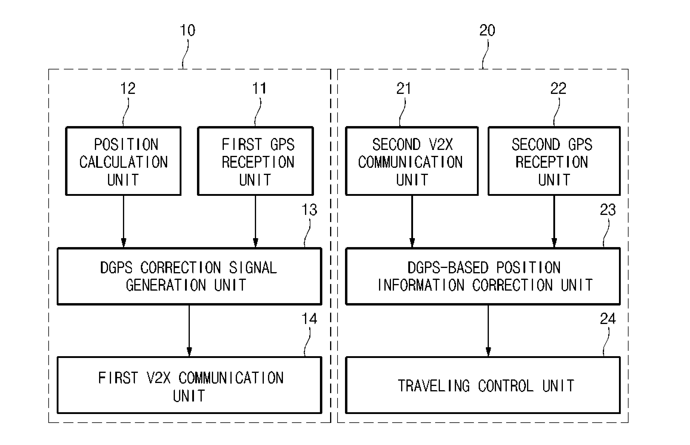
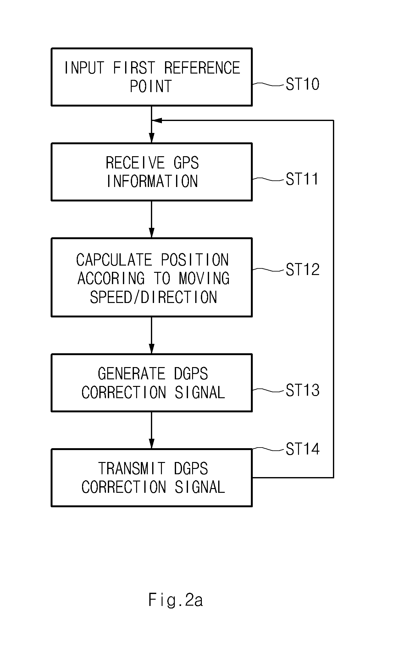
A method and system of controlling a relative position between vehicles using a mobile base station is provided. GPS information is received from a satellite at a mobile base station and a target vehicle. The current position information the mobile base station is calculated with reference to a moving speed and direction based on the received GPS information. DGPS correction data is then generated by calculating the calculated position information and the received GPS information through a preset algorithm and the generated DGPS correction data is transmitted to one or more target vehicles. In the control target vehicle, the transmitted DGPS correction data is received, GPS information is received from a satellite, position information is calculated based on the received GPS information and the received DGPS correction data to execute position correction, and a speed and direction of the control target vehicle is adjusted according to the calculated position information.

Description

CROSS-REFERENCES TO RELATED APPLICATIONS[0001]This application claims priority to Korean patent application No. 10-2011-0115279 filed on Nov. 7, 2011, the disclosure of which is hereby incorporated in its entirety by reference.BACKGROUND OF THE INVENTION[0002]1. Field of the Invention[0003]The present invention relates to technology for controlling a relative position between vehicles, and more particularly, to a method and system of controlling a relative position between vehicles using a mobile base station, which improves the accuracy of a relative position between vehicles and performs position control while communicating with a vehicle serving as a mobile base station of a differential global positioning system (DGPS) through vehicle to vehicle (V2X) communication.[0004]2. Description of the Related Art[0005]The Global Positioning System (GPS) is a space-based satellite navigation system that provides location and time information to remote devices located anywhere on or near t...

Claims


Application Information

Patent Timeline
IPC IPC(8): G05D1/00
CPCG01S19/07G01S19/41G05D1/027H04W4/027G05D1/0295G05D2201/0213G05D1/0278G01S19/071
Inventor OH, YOUNG CHULJANG, YOON HOIM, SEONG SUSUNG, SU LYUN
Owner HYUNDAI MOTOR CO LTD
Learn More